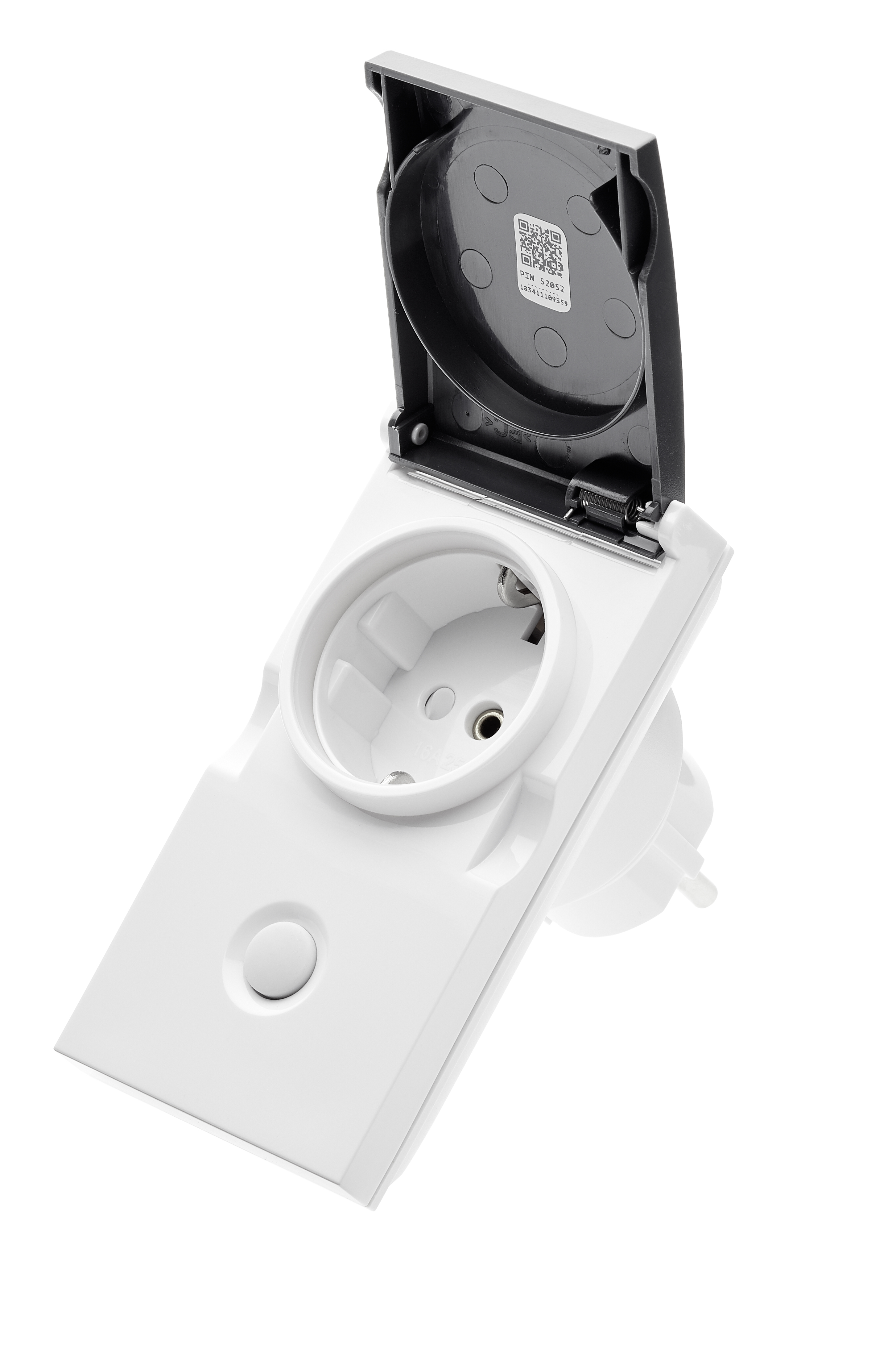
Smart Outdoor Plug
SKU: POPE700397
Quickstart
This is a
Important safety information
Please read this manual carefully. Failure to follow the recommendations in this manual may be dangerous or may violate the law. The manufacturer, importer, distributor and seller shall not be liable for any loss or damage resulting from failure to comply with the instructions in this manual or any other material. Use this equipment only for its intended purpose. Follow the disposal instructions. Do not dispose of electronic equipment or batteries in a fire or near open heat sources.What is Z-Wave?
Z-Wave is the international wireless protocol for communication in the Smart Home. This device is suited for use in the region mentioned in the Quickstart section.
Z-Wave ensures a reliable communication by reconfirming every message (two-way communication) and every mains powered node can act as a repeater for other nodes (meshed network) in case the receiver is not in direct wireless range of the transmitter.
This device and every other certified Z-Wave device can be used together with any other certified Z-Wave device regardless of brand and origin as long as both are suited for the same frequency range.
If a device supports secure communication it will communicate with other devices secure as long as this device provides the same or a higher level of security. Otherwise it will automatically turn into a lower level of security to maintain backward compatibility.
For more information about Z-Wave technology, devices, white papers etc. please refer to www.z-wave.info.
Product Description
Switching is controlled by the local button or wirelessly. The use of the local button and the behavior on wireless commands can be configured using configuration parameters. When detached from the control of local leads the button on the device can be used to trigger scenes in a central gateway. A single click and double click are distinguished.
The device is also measuring the mains voltage supply reporting mains voltage and mains frequency. Additionally, the power consumption of the attached load is monitored as well.
All metering values can be requested from the central controller and will be reported unsolicited if configured.
Prepare for Installation / Reset
Please read the user manual before installing the product.
In order to include (add) a Z-Wave device to a network it must be in factory default state. Please make sure to reset the device into factory default. You can do this by performing an Exclusion operation as described below in the manual. Every Z-Wave controller is able to perform this operation however it is recommended to use the primary controller of the previous network to make sure the very device is excluded properly from this network.
Reset to factory default
This device also allows to be reset without any involvement of a Z-Wave controller. This procedure should only be used when the primary controller is inoperable.
Safety Warning for Mains Powered Devices
ATTENTION: only authorized technicians under consideration of the country-specific installation guidelines/norms may do works with mains power. Prior to the assembly of the product, the voltage network has to be switched off and ensured against re-switching.
Installation
The device can be plugged into every standard power outlet Type F. Thanks to IP44 rating this device can be used in wet environments such as bathrooms or basements and even outdoor. Do not stack the device!
Inclusion/Exclusion
On factory default the device does not belong to any Z-Wave network. The device needs to be added to an existing wireless network to communicate with the devices of this network. This process is called Inclusion.
Devices can also be removed from a network. This process is called Exclusion. Both processes are initiated by the primary controller of the Z-Wave network. This controller is turned into exclusion respective inclusion mode. Inclusion and Exclusion is then performed doing a special manual action right on the device.
Inclusion
Exclusion
Product Usage
The device is able to switch electric loads up to 3500 W and can be switched wirelessly or using the local button. The connected load is measured and reported. Trigger values can define unsolicited power reports. The device includes a virtual circuit breaker. The configuration values 26-28 define the behavior of this function. Depending on the configuration parameter 4 the local button with either control the local load or sends scene activation commands to the central gateway.
Quick trouble shooting
Here are a few hints for network installation if things dont work as expected.
- Make sure a device is in factory reset state before including. In doubt exclude before include.
- If inclusion still fails, check if both devices use the same frequency.
- Remove all dead devices from associations. Otherwise you will see severe delays.
- Never use sleeping battery devices without a central controller.
- Dont poll FLIRS devices.
- Make sure to have enough mains powered device to benefit from the meshing
Firmware-Update over the Air
This device is capable of receiving a new firmware 'over the air'. The update function needs to be supported by the central controller. Once the controller starts the update process, perform the following action to confirm the firmware update: Single Click the button to confirm the update
Association - one device controls an other device
Z-Wave devices control other Z-Wave devices. The relationship between one device controlling another device is called association. In order to control a different device, the controlling device needs to maintain a list of devices that will receive controlling commands. These lists are called association groups and they are always related to certain events (e.g. button pressed, sensor triggers, ...). In case the event happens all devices stored in the respective association group will receive the same wireless command wireless command, typically a 'Basic Set' Command.
Association Groups:
| Group Number | Maximum Nodes | Description |
|---|---|---|
| 1 | 5 | Lifeline |
| 2 | 5 | Control other devices on single click of the button. BASIC command (on/off) is sent according to switching state of the load. |
Configuration Parameters
Z-Wave products are supposed to work out of the box after inclusion, however certain configuration can adapt the function better to user needs or unlock further enhanced features.
IMPORTANT: Controllers may only allow configuring signed values. In order to set values in the range 128...255 the value sent in the application shall be the desired value minus 256. For example: To set a parameter to 200 it may be needed to set a value of 200 minus 256 = minus 56. In case of a two byte value the same logic applies: Values greater than 32768 may needed to be given as negative values too.
Parameter 1: LED Operation Mode
Defines when the LED shall shine and how Size: 1 Byte, Default Value: 1
| Setting | Description |
|---|---|
| 0 | LED off, only blinks on traffic |
| 1 | Defined by Parameter 21 and 22 |
Parameter 2: Auto Off
Defines if and after which time the device shall turn off without any user interaction Size: 2 Byte, Default Value: 0
| Setting | Description |
|---|---|
| 0 | no auto off |
| 1 - 65535 | seconds |
Parameter 3: Switching behavior when receiving wireless OFF
Size: 1 Byte, Default Value: 0
| Setting | Description |
|---|---|
| 0 | Switches off |
| 1 | Ignores Off command |
| 2 | Switches on |
| 3 | Switches on, when receiving off command and current state is off |
Parameter 4: Button Mode
This parameter defines if the local button shall control (switch) the load or it is only used to send out scene control commands to the central controller. Size: 1 Byte, Default Value: 0
| Setting | Description |
|---|---|
| 0 | Controls Load + Controls Scenes |
| 1 | Scene Control Only |
Parameter 5: Status after Power Failure
Defines the switching status after a power failure or unplugging Size: 1 Byte, Default Value: 1
| Setting | Description |
|---|---|
| 0 | Always off |
| 1 | Return to last switching state |
Parameter 21: LED Color on OFF state
Defines the behavior of the LED when the load is switched off Size: 1 Byte, Default Value: 0
| Setting | Description |
|---|---|
| 0 | Off |
| 1 | Red |
| 2 | Green |
Parameter 22: LED Color on ON state
Defines the behavior of the LED when the load is switched on Size: 1 Byte, Default Value: 2
| Setting | Description |
|---|---|
| 0 | Off |
| 1 | Red |
| 2 | Green |
Parameter 23: Voltage Report Threshold
Report the voltage when the voltage has changed by more then X * 1 V. When disabled the device will report every 10 minutes regardless of current voltage. Size: 1 Byte, Default Value: 100
| Setting | Description |
|---|---|
| 0 | Disabled |
| 1 - 250 | Volt |
Parameter 24: Current Reporting Threshold
Report the current when the current has changed by more then X *0,01 A. When disabled the device will report every 10 minutes regardless of current change. Size: 1 Byte, Default Value: 10
| Setting | Description |
|---|---|
| 0 | Disabled |
| 1 - 255 | * 0,01 A |
Parameter 25: Power Reporting Threshold
Report the power when the power has changed by more then X Watt. When disabled the device will report every 10 minutes regardless of power consumption change. Size: 1 Byte, Default Value: 50
| Setting | Description |
|---|---|
| 0 | Disabled |
| 1 - 255 | W |
Parameter 26: Soft Circuit Breaker Threshold
When the power draw exceeds the value set in this parameter for a time set in parameter 28 the soft ciruit breaker will disconnect the load. Size: 2 Byte, Default Value: 3600
| Setting | Description |
|---|---|
| 0 | Disabled |
| 1 - 3600 | W |
Parameter 27: Soft Circuit Breaker Recovery Time
Once the soft circuit breaker tipps and the load is disconnected the load will be automatically reconneced after X seconds. When disabled the load must be repowered manually or with wireless command. Size: 1 Byte, Default Value: 0
| Setting | Description |
|---|---|
| 0 | Never |
| 1 - 255 | sec. |
Parameter 28: Soft Circuit Breaker Delay Time
This delay time defines how fast the soft circuit breaker wil react when the threshold power is exceeded. The power is cut off only if the power draw remains over the threshold level for the defines time. Size: 1 Byte, Default Value: 10
| Setting | Description |
|---|---|
| 0 - 255 | * 0,1 sec |
Technical Data
| Dimensions | 114x59x92 mm mm |
| Weight | 153 gr |
| Hardware Platform | ZM5101 |
| EAN | 4251295700397 |
| IP Class | IP IP44 |
| Voltage | 230V |
| Load | 3500 W |
| Device Type | On/Off Power Switch |
| Generic Device Class | Binary Switch |
| Specific Device Class | Binary Power Switch |
| Firmware Version | 03.01 |
| Z-Wave Version | 6.01 |
| Certification ID | ZC10-18026015 |
| Z-Wave Product Id | 0x0154.0x0003.0x000a |
Supported Command Classes
- Basic
- Switch Binary (s2 Unauth);
- Class Sensor Multilevel (s2 Unauth)
- Meter (s2 Unauth)
- Association Grp Info (s2 Unauth)
- Device Reset Locally (s2 Unauth)
- Central Scene (s2 Unauth)
- Zwaveplus Info
- Supervision
- Configuration (s2 Unauth)
- Manufacturer Specific (s2 Unauth)
- Powerlevel (s2 Unauth)
- Protection (s2 Unauth)
- Firmware Update Md (s2 Unauth)
- Association (s2 Unauth)
- Version (s2 Unauth)
- Multi Channel Association (s2 Unauth)
- Security 2
- Transport Service
Explanation of Z-Wave specific terms
- Controller — is a Z-Wave device with capabilities to manage the network. Controllers are typically Gateways,Remote Controls or battery operated wall controllers.
- Slave — is a Z-Wave device without capabilities to manage the network. Slaves can be sensors, actuators and even remote controls.
- Primary Controller — is the central organizer of the network. It must be a controller. There can be only one primary controller in a Z-Wave network.
- Inclusion — is the process of adding new Z-Wave devices into a network.
- Exclusion — is the process of removing Z-Wave devices from the network.
- Association — is a control relationship between a controlling device and a controlled device.
- Wakeup Notification — is a special wireless message issued by a Z-Wave device to announces that is able to communicate.
- Node Information Frame — is a special wireless message issued by a Z-Wave device to announce its capabilities and functions.
Support and Contact
Should you encounter any problem, please give us an opportunity to address it before returning this product. Most questions regarding Z-Wave wireless communication standard can be answered through the international users community such as www.z-wave.info and others. If your question can’t be answered there, please use our Popp Z-Wave site
While the information in this manual has been compiled with great care, it may not be deemed an assurance of product characteristics. Popp & Co. shall be liable only to the degree specified in the terms of sale and delivery. The reproduction and distribution of the documentation and software supplied with this product and the use of its contents is subject to written authorization from Popp & Co. We reserve the right to make any alterations that arise as the result of technical development.
eMail: [email protected]
Web: Popp.eu
Declaration of Conformity
![]() Popp hereby declares this
device complies with the essential requirements and other relevant prescriptions of
Directive 1999/5/EC R&TTE. The complete CE declaration can be found on:
www.popp.eu/ce.
Popp hereby declares this
device complies with the essential requirements and other relevant prescriptions of
Directive 1999/5/EC R&TTE. The complete CE declaration can be found on:
www.popp.eu/ce.
All questions regarding this declaration of conformity can be directed to the following address: Z-Wave Europe GmbH, Neefestr. 147, 09116 Chemnitz, Germany
Disposal Guidelines
![]() Do not dispose of electrical appliances as unsorted municipal waste, use
separate collection facilities. Contact your local government for
information regarding the collection systems available. If electrical
appliances are disposed of in landfills or dumps, hazardous substances can
leak into the groundwater and get into the food chain, damaging health and
well-being.
Do not dispose of electrical appliances as unsorted municipal waste, use
separate collection facilities. Contact your local government for
information regarding the collection systems available. If electrical
appliances are disposed of in landfills or dumps, hazardous substances can
leak into the groundwater and get into the food chain, damaging health and
well-being.