ABUS
Hometec Z-Wave CFA3010
SKU: ABUECFA3010S


Quickstart
This is a
The device also supports Smart Start. Please scan the QR code on the outlet cover of the device and your controller will add the device automatically when powered up.
SmartStart enabled products can be added into a Z-Wave network by scanning the Z-Wave QR Code present on the product with a controller providing SmartStart inclusion. No further action is required and the SmartStart product will be added automatically within 10 minutes of being switched on in the network vicinity.
Important safety information
Please read this manual carefully. Failure to follow the recommendations in this manual may be dangerous or may violate the law. The manufacturer, importer, distributor and seller shall not be liable for any loss or damage resulting from failure to comply with the instructions in this manual or any other material. Use this equipment only for its intended purpose. Follow the disposal instructions. Do not dispose of electronic equipment or batteries in a fire or near open heat sources.Product Description
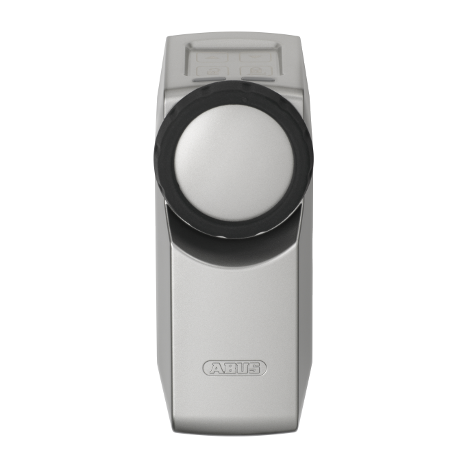
The HomeTec Z-Wave wireless door lock actuator is a system designed for retrofitting to doors that open inwards to provide motorized locking and unlocking functions. The door can be electronically operated using local buttons and any Z-Wave device capable to control door locks. For the wireless door lock actuator to work, the cylinder must project 7-12 mm on the inside of the door (plus the thickness of the fitting or collar). Because the actuator operates with a key permanently inserted in the lock, the cylinder must have an emergency feature where the door can be opened with a key from the outside even when another key is inserted on the inside. In addition, the door lock must be a profile cylinder compliant with DIN 18252. This device is security enabled Z-Wave Plus product that is able to use encrypted Z-Wave Plus messages to communicate to other security enabled Z-Wave Plus products. This device must be used in conjunction with a Security Enabled Z-Wave Controller in order to fully utilize all implemented functions.
Installation
A particular plus point is that the device can be built in without needing to use a special cylinder. So you can integrate it into an existing locking system. The only requirement is that the door cylinder must be a cylinder with an emergency and danger function. This function is extremely important. As it ensures that you can unlock your front door with your normal house key when required. In addition, there should be a cylinder projection of at least 7 to max. 12 millimeters on the inside so that the HomeTec Pro can be built in quickly without any problems.
Enable Fallback to S0 Security
The device will not allow legacy security S0 on default. If you like to operate the device with a controller not supporting S2 security you need to enable fallback into S0.
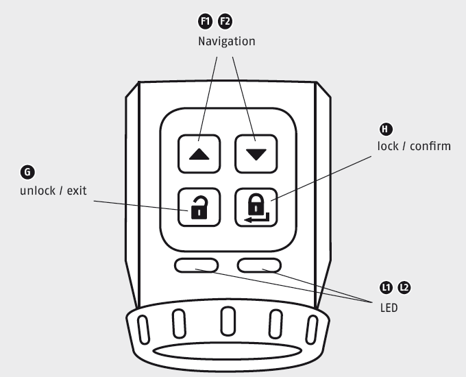
- Enable management mode by holding down F1 and F2 for 3 seconds. Green left LED will light up to confirm management mode.
- Again pushing F1 and F2 for 3 seconds to enter Menu mode. Green left LED will blink to confirm.
- Move in this menu by pushing F1 or F2 Arrows. The left LED will change its color to indicate different menu items.
left LED = yellow: Speed settings,
left LED = green: Power settings,
left LED = red: Z-Wave Security - Enter the menu, where left LED blinks RED, by pushing F1 or F2 Arrows.
- Hit "Enter" (door close button). Now you will see the actual status of S0 fallback: right LED = red: S2+S0, right LED = green: S2 only
- Using the keys F1 and F2 you can change the setting. Change the setting to be RED (S2 + S0)
- Confirm selection with "Enter" (door close button)
- Leave the menu by clicking "door open". Leave the management mode by clicking "door open" again
Physical installation on the door
more information from ABUS Hometec original manual.
Product Usage
This door lock can be operated by a central Z-Wave enabled controller (using e.g. mobile phone), a dedicated Z-Wave remote control and from local buttons. Once installed. The Home Tec can turn the door lock to open and close. In parallel legacy operation using a key from the outside remains possible. The local buttons "door open" and
"door close". accessible from the inside allows convenient locking and unlocking the key. It is possible to just close the door and really lock it up moving the deadbolt into the "close" position.
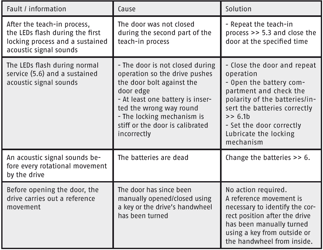
The device sends the following notifications to the central controller:
- Lock Jammed (0x06 - 0x0B)
- Hardware Failure (0x09 - 0x01)
- Motor Overcurrent (0x08 - 0x06)
- Replace batteries (0x08 - 0x0B)
- Door Unsecured (0x00)
- Door Unsecured with Timeout (0x01)
- Door Secured (0xFF)
- Constant Operation (0x01)
- Timed Operation (0x02)
By default the Door Lock has the following configuration:
Operation Type: Timed Operation (0x02)
Lock Timeout Minutes: 0x00
Lock Timeout Seconds: 0x1E (30)
The Door Lock can be operated:
- Remotely using Z-Wave radio commands
- Manually using Lock and Unlock buttons, located on the handle
- Manually using the drives handwheel. This brings the lock to an "unknown" state and requires an additional open/close action using the Z-Wave radio commands or lock/unlock buttons
- Manually using the key from outside. This brings the lock to an "unknown" state and requires an additional open/close action using the Z-Wave radio commands or lock/unlock buttons
Calibration procedure
After a reset procedure, the user must do the recalibration of the lock mechanism.
The calibration procedure must be performed, as described below. Otherwise correct behavior of the device is not guaranteed.
To calibrate the door lock:
- Physically open the door, where Door Lock is mounted
- Enable management mode by holding down F1 and F2 for 3 seconds. Both LEDs will start blinking yellow, indicating, that lock awaits calibration procedure
- Hit "Enter" (button with closed door symbol).
- The lock will start open/close calibrating procedure, which takes about 3-10seconds. Both LEDs will continue blinking yellow
- Physically close the door, where Door Lock is mounted
- Hit "Enter" (button with closed door symbol).
- The lock will start open/close calibrating procedure, which takes about 3-10seconds.
- Both LEDs should stop blinking yellow and become idle. If LEDs are still blinking, retry the calibration procedure
| Reset to factory default |
All settings are deleted. Configuration parameters are NOT reset to default values. The user must explicitly reset them |
| Inclusion |
|
| Exclusion |
|
| NIF | XXXNIF |
| Wakeup | XXXWakeupDescription |
| Protection | XXXProtection |
| FirmwareUpdate |
If/when completed successfully (Firmware Update procedure might take up to 10 minutes) the LEDs will blink GREEN and return to normal operation. |
| SetAssociation | XXXSetAssociation |
Association Groups:
| Group Number | Maximum Nodes | Description |
|---|---|---|
| 1 | 5 | Lifeline |
Configuration Parameters
Parameter 1: Latch Hold Time
This parameter defines how long the latch is hold open when the door hall be opened. Size: 1 Byte, Default Value: 3
| Setting | Description |
|---|---|
| 1 - 20 | seconds |
Parameter 2: Latch Torque
This parameter defines the torque of the latch. Size: 1 Byte, Default Value: 2
| Setting | Description |
|---|---|
| 1 | Torque of the latch is high (max.) |
| 2 | Torque of the latch is medium |
| 3 | Torque of the latch is low (min.) |
Parameter 3: Acoustic Feedback
This parameter defines Acoustic Feedback signals. Size: 1 Byte, Default Value: 3
| Setting | Description |
|---|---|
| 1 | Acoustic signal is inactive |
| 2 | Acoustic signal only at the beginning of the lock travel |
| 3 | Acoustic signal when reaching the position of the event |
| 4 | Acoustic signal when reaching the position Locked |
| 5 | Acoustic signal when reaching each end position |
Parameter 4: Travel Time
This parameter defines the travel path of the Lock. Size: 1 Byte, Default Value: 1
| Setting | Description |
|---|---|
| 1 | Automatic/Normal |
| 2 | Multiple turns for one Open/Close action |
| 3 | Travel from Tilted Position is turned on |
Parameter 5: Touch Panel Settings
This parameter defines Touch Panel settings Size: 1 Byte, Default Value: 1
| Setting | Description |
|---|---|
| 1 | Touch Panel is active |
| 2 | Only Touch Panel Control Buttons are active |
| 3 | Touch Panel is inactive |
| 4 | Touch Panel Trap is inactive |
Parameter 6: Motor Force
This parameter defines the motor force, when turning the lock. Size: 1 Byte, Default Value: 1
| Setting | Description |
|---|---|
| 1 | Automatic / Normal force |
| 2 | Maximum force |
Parameter 250: Lock status
Size: 1 Byte, Default Value: 0
| Setting | Description |
|---|---|
| 0 | unknown |
| 1 | open |
| 2 | unlocked |
| 3 | 1x locked |
| 4 | 2x locked |
| 5 | locked (end stop) |
| 6 | multiple interlocked |
Parameter 251: Drive cycles Trap
Counter, how often the trap is activated was. Size: 4 Byte, Default Value: 0
| Setting | Description |
|---|---|
| 0 - 1670000 | Counter |
Parameter 252: driving cycles unlocked
Counter, how often in the direction of Unlocked navigated was. Size: 4 Byte, Default Value: 0
| Setting | Description |
|---|---|
| 0 - 1670000 | Counter |
Parameter 153: Driving cycles interlocked
Counter, how often in the direction of Locked. navigated was. Size: 4 Byte, Default Value: 0
| Setting | Description |
|---|---|
| 0 - 1670000 | Counter |
Parameter 254: ABUS Firmware Version
Display of ABUS Firmware version, e.g. 1.05 Size: 2 Byte, Default Value: 0
| Setting | Description |
|---|---|
| 0 - 65535 | Version |
Technical Data
| Dimensions | 138 x 51 x 66 mm |
| Weight | 260 gr |
| Hardware Platform | ZM5101 |
| EAN | 4003318829673 |
| IP Class | IP 20 |
| Voltage | 6V |
| Battery Type | 4 * AA |
| Device Type | Door Lock |
| Network Operation | Listening Sleeping Slave |
| Firmware Version | 1.0 |
| Z-Wave Version | 06.01 |
| Certification ID | ZC10-19076649 |
| Z-Wave Product Id | 0409.0005.0003 |
| Frequency | Europe - 868,4 Mhz |
| Maximum transmission power | 5 mW |