Aeon Labs
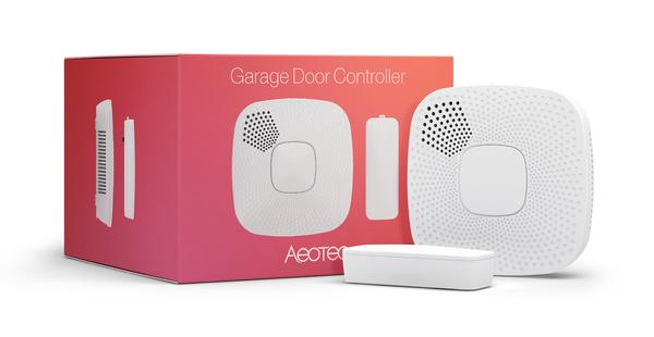
Garage Door Controller
SKU: AEOEZW062


Quickstart
This is a
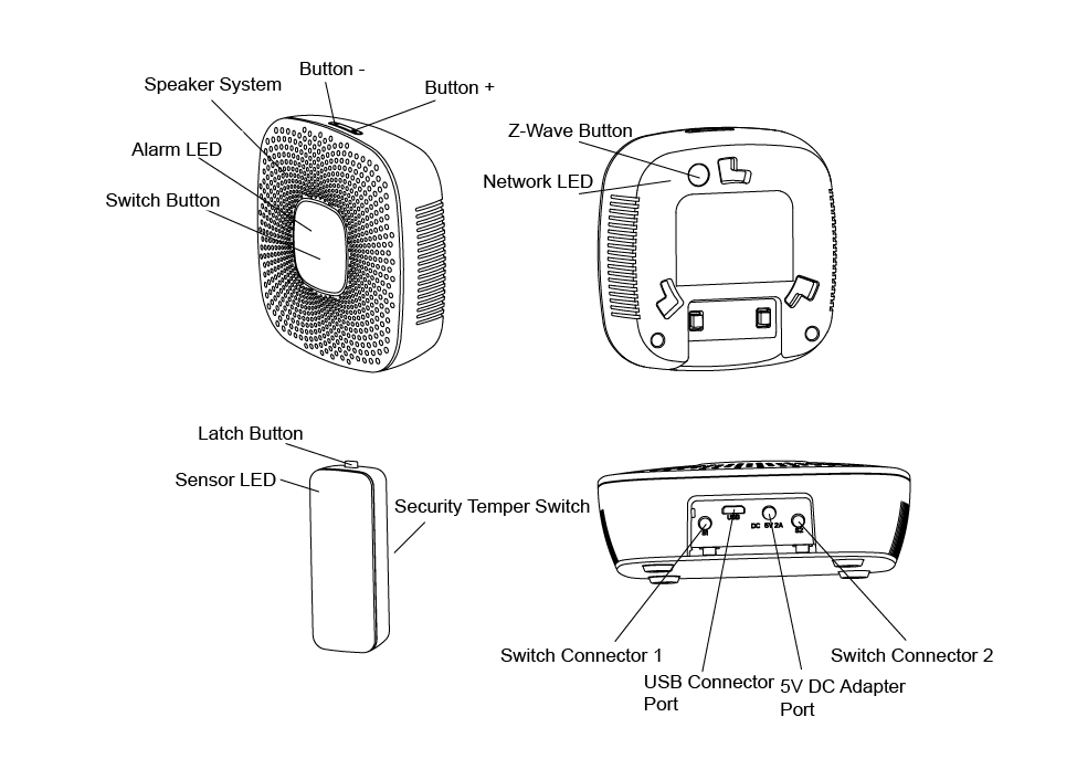
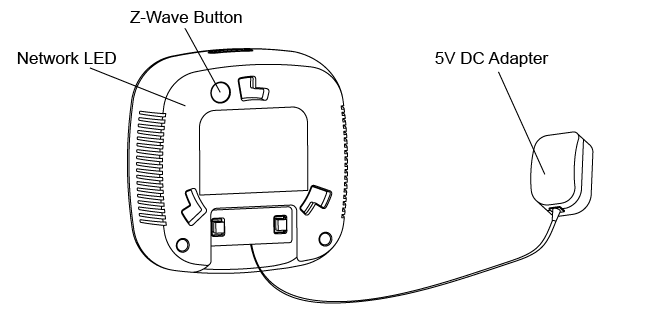
A To include the device turn the primary controller of Z-Wave network into inclusion mode, short press the product?s Z-Wave button that you can find on the product"s housing.
Important safety information
Please read this manual carefully. Failure to follow the recommendations in this manual may be dangerous or may violate the law. The manufacturer, importer, distributor and seller shall not be liable for any loss or damage resulting from failure to comply with the instructions in this manual or any other material. Use this equipment only for its intended purpose. Follow the disposal instructions. Do not dispose of electronic equipment or batteries in a fire or near open heat sources.Product Description
Aeon Labs Garage Door Controller is a smart and wireless Garage Door Control system, you can control the garage door to open, close, or stop moving via wireless signal on your gateway client or phone application.
Installation
The Garage Door Controller must be installed in your home and near the garage door. It cannot be installed outdoors in elements such as rain and snow.
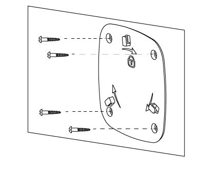
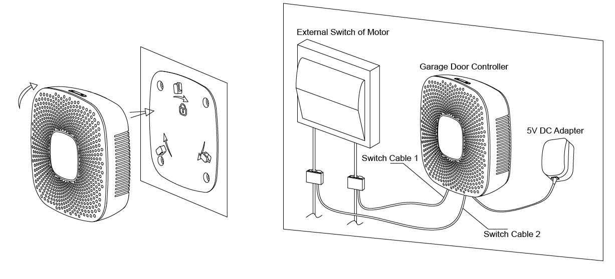
- Utilize the provided 20mm screws to affix it to the desired surface.
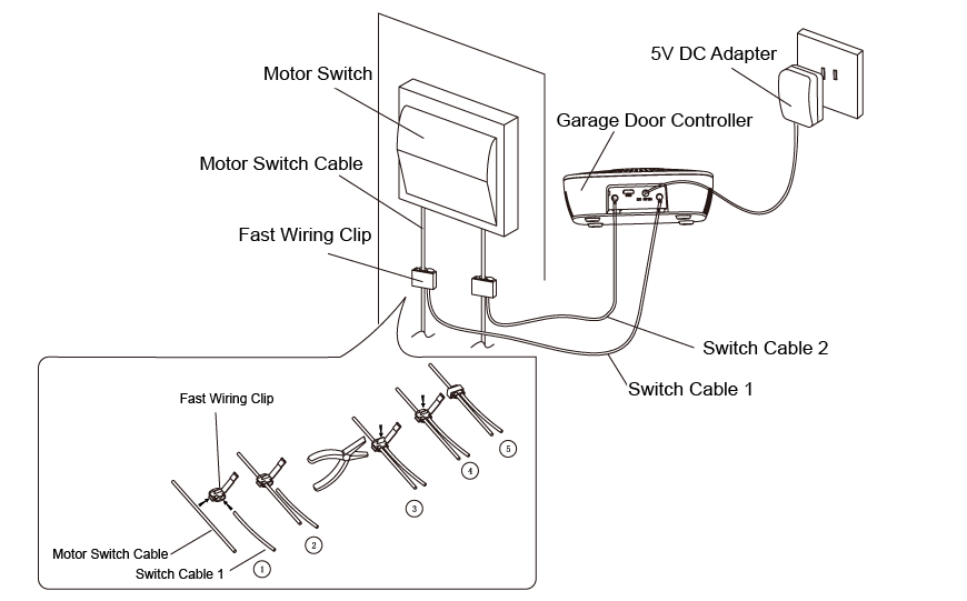
- Connect the 2 Switch cables to the Switch Connector 1 and 2 on the Garage Door Controller, and then use the Fast Wiring Clip to connect the 2 Switch Cables to the Motor Switch Cables, see the figure below.
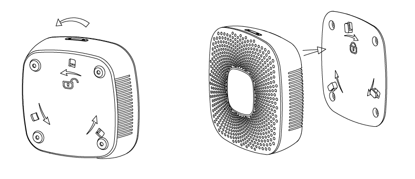
- Now lock the Garage Door Controller to the Back Mount Plate by twisting the Garage Door Controller.
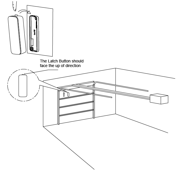
Affix your sensor mounting plate to the garage door. The sensor mount plate should be installed on the top of the garage door (on the left, middle, or right side). Now affix your sensor mounting plate to the surface. Your mounting plate can be affixed using screws or double-sided tape. If you are using screws, attach the mounting plate to the respective surface using the two 20mm screws provided.
Product Usage
Unlock the Back Mount Plate of Garage Door Controller by twisting the Back Mount Plate and separating the two parts of your Garage Door Controller.
Power your Garage Door Controller by connecting the 5V DC Adapter to the input.
| Reset to factory default | To reset the device press and hold the Z-Wave Button for 20 seconds and then release it. Your Garage Door Controller will now be reset to its original settings, and the Network LED will be solid for 2 seconds and then start slow blinking to confirm a success. |
| Inclusion | 1. Install the device according to the instructions. 2. Press the button on the back of the garage door controller. |
| Exclusion | 1. Press the button 3 times on the back of the garage door controller. |
| NIF | XXXNIF |
| Wakeup | XXXWakeupDescription |
| Protection | XXXProtection |
| FirmwareUpdate | XXXFirmwareUpdate |
| SetAssociation | XXXSetAssociation |
Association Groups:
| Group Number | Maximum Nodes | Description |
|---|---|---|
| 1 | 5 | Group 1 is assigned to the Lifeline association group and every device has 5 nodes to associate. When the Garage Door controller is received the commands sent by controller to be turned on or off, the Garage Door controller will send a basic report of its status to the nodes in association group 1. To change what kind of signal is sent to the nodes in group 1, please see the detailed description of configuration parameter 80. |
| 2 | 5 | When the Garage Door Controller receives the Basic Set, Switch Binary Set,commands from main controller. it will forward the Basic Set, Switch Binary Set to associated nodes in Group 2. |
Configuration Parameters
Parameter 32: Startup ringtone
Configure the Startup ringtone Size: 1 Byte, Default Value: 1
| Setting | Description |
|---|---|
| 0 | Disable |
| 1 - 100 | Enable the Startup ringtone. |
Parameter 34: Sensor Calibration
1. Let the garage door move to full close position. 2. Send this parameter (0x22) with ?value=1? to Garage Door Controller. 3. Let the garage door move to full open position. 4. Let the garage door move to full close position after the step 3 is completed. After the step 4 is completed, all calibration steps are complete. Size: 1 Byte, Default Value: 0
| Setting | Description |
|---|---|
| 1 | Start calibration |
Parameter 35: Timeouts
Set the timeout of all calibration steps for the Sesnor. Size: 2 Byte, Default Value: 60
| Setting | Description |
|---|---|
| 1 - 65535 | Time in seconds |
Parameter 36: Alarm musik
Get the numbers of alarm music.?does not support Set CC Size: 1 Byte, Default Value: 01
| Setting | Description |
|---|
Parameter 37: Alarm mode for door opening
Value1: configure the frequency of blinking for the Alarm LED?there are 10 levels that 1 to10 level, the minimum frequency is level 1 and the max frequency is level 10. Value2: configure the alarm sound (there are 4 types sound saved in EEPROM and user also can update it). Value3: configure the volume of alarm sound (there are 10 levels, the min volume is 1 level and the max volume is 10 levels). Value4=0, disable the alarm prompt. Value4=1, enable the alarm prompt. Size: 4 Byte, Default Value: 0
| Setting | Description |
|---|---|
| 1 - 10 | Configure the alarm LED interval. |
| 256 - 356 | Select an alarm tone. Four alarm tones are stored on the memory card. |
| 65535 - 65545 | Adjust the volume of the alarm tone. There are 10 levels. |
| 1677215 | Deactivate the alarm mode. |
| 16777216 | Activate the alarm mode. |
Parameter 38: alarm mode for door closing
Value1: configure the frequency of blinking for the Alarm LED?there are 10 levels that 1 to10 level, the minimum frequency is level 1 and the max frequency is level 10. Value2: configure the alarm sound (there are 4 types sound saved in EEPROM and user also can update it). Value3: configure the volume of alarm sound (there are 10 levels, the min volume is 1 level and the max volume is 10 levels). Value4=0, disable the alarm prompt. Value4=1, enable the alarm prompt. Size: 4 Byte, Default Value: 6
| Setting | Description |
|---|---|
| 1 - 10 | Configure the alarm LED interval. |
| 256 - 356 | Select an alarm tone. Four alarm tones are stored on the memory card. |
| 65535 - 65545 | Adjust the volume of the alarm tone. There are 10 levels. |
| 1677215 | Deactivate the alarm mode. |
| 16777216 | Activate the alarm mode. |
Parameter 39: Prompt mode of unknown state:
Value1: configure the frequency of blinking for the Alarm LED?there are 10 levels that 1 to10 level, the minimum frequency is level 1 and the max frequency is level 10. Value2: configure the alarm sound (there are 4 types sound saved in EEPROM and user also can update it). Value3: configure the volume of alarm sound (there are 10 levels, the min volume is 1 level and the max volume is 10 levels). Value4=0, disable the alarm prompt. Value4=1, enable the alarm prompt. Size: 4 Byte, Default Value: 0
| Setting | Description |
|---|---|
| 1 - 10 | Configure the alarm LED interval. |
| 256 - 356 | Select an alarm tone. Four alarm tones are stored on the memory card. |
| 65535 - 65545 | Adjust the volume of the alarm tone. There are 10 levels. |
| 1677215 | Deactivate the alarm mode. |
| 16777216 | Activate the alarm mode. |
Parameter 40: Prompt mode of full closing
Value1: configure the frequency of blinking for the Alarm LED?there are 10 levels that 1 to10 level, the minimum frequency is level 1 and the max frequency is level 10. Value2: configure the alarm sound (there are 4 types sound saved in EEPROM and user also can update it). Value3: configure the volume of alarm sound (there are 10 levels, the min volume is 1 level and the max volume is 10 levels). Value4=0, disable the alarm prompt. Value4=1, enable the alarm prompt. Size: 4 Byte, Default Value: 0
| Setting | Description |
|---|---|
| 1 - 10 | Configure the alarm LED interval. |
| 256 - 356 | Select an alarm tone. Four alarm tones are stored on the memory card. |
| 65535 - 65545 | Adjust the volume of the alarm tone. There are 10 levels. |
| 1677215 | Deactivate the alarm mode. |
| 16777216 | Activate the alarm mode. |
Parameter 41: Tamper report
Size: 1 Byte, Default Value: 0
| Setting | Description |
|---|---|
| 0 | Sensor is not removed (read only) |
| 16 | Sensor 1 is removed (read only) |
| 240 | Sensor 2 is removed (read only) |
| 1431655767 | Alarm reset (write only) |
Parameter 42: Battery report (read only)
Use this configuration report to report the battery power state of Sensor Size: 1 Byte, Default Value: 0
| Setting | Description |
|---|---|
| 0 | Battery power is much more. |
| 16 | Battery power of Sensor 1 is in low battery. |
| 240 | battery power of Sensor 2 is in low battery |
Parameter 43: Play/stop music
Play/stop music, which can be used to audition/test the music Size: 1 Byte, Default Value: 0
| Setting | Description |
|---|---|
| 1 - 254 | Play the music that you selected. |
| 255 | Stop playing music. |
Parameter 44: Volume
Set the volume, which can be used to audition/test volume of music Size: 1 Byte, Default Value: 0
| Setting | Description |
|---|---|
| 1 - 10 | Volume |
Parameter 45: Environment temperature (read only)
The report values that have 4 bytes and its accuracy is 1/1000 after be converted to decimal. Size: 2 Byte, Default Value: 0
| Setting | Description |
|---|
Parameter 46: Blinking frequency of alarm LED.
Size: 1 Byte, Default Value: 0
| Setting | Description |
|---|---|
| 1 - 10 | blinking frequency of alarm LED. |
Parameter 47: Button +/-
Size: 1 Byte, Default Value: 0
| Setting | Description |
|---|---|
| 0 | Short pressing the ?Button +/-? will be used to adjust 0 1 9 the volume of sound. Long pressing the ?Button +/-? will be used to switch the sound to the next. |
| 1 | Short pressing the ?Button +/-? will be used to switch the sound to the next. Long pressing the ?Button +/-? will be used to adjust the volume of sound. |
Parameter 80: Hail CC/configuration report
It will send the Hail CC/configuration report CC when the state of garage door is changed Size: 1 Byte, Default Value: 2
| Setting | Description |
|---|---|
| 0 | not send |
| 1 | send Hail CC |
| 2 | send configuration report CC |
| 3 | Send Hail CC when the garage door state is changed just only by wireless control. |
Parameter 200: Partner ID
Size: 1 Byte, Default Value: 0
| Setting | Description |
|---|
Parameter 241: Pair the Sensor with Garage Door Controller
Send Configuration Set Value=0x55555501, which will trigger to start the pairing of Sensor (installed on the top of the garage door), at this time, the Network LED on the Garage Door Controller will blink slowly and then short press Temper Switch back of the Sensor. If pairing is successful, the Network LED will stop blinking and the Garage Door Controller will send the configuration report with value=0x01FF to primary controller/gateway. Otherwise, repeat the operation. Note: 1. If you do not press the Temper Switch when starting the pairing mode, the pairing status will keep for 8 second and then exit the pairing status automatically. 2. The Sensor has been paired with the Garage Door Controller after factory. Size: 4 Byte, Default Value: 0
| Setting | Description |
|---|---|
| 0 | Enable |
Parameter 252: Enable/disable configuration locked
Size: 1 Byte, Default Value: 0
| Setting | Description |
|---|---|
| 0 | Aktiviert |
| 1 | Disable |
Parameter 255: Factory Reset
Size: 4 Byte, Default Value: 1
| Setting | Description |
|---|---|
| 0 | Reset All configurations to default value. |
| 1431655765 | Reset to default factory setting and send the Device Reset Locally CC. |
Technical Data
| Dimensions | 0.1160000x0.1160000x0.0330000 mm |
| Weight | 170 gr |
| EAN | 1220000012646 |
| IP Class | IP 20 |
| Voltage | 5V DC for Garage Door Controller |
| Load | 2W |
| Battery Type | 1 * CR2 3V 800mA for Sensor |
| Device Type | On/Off Power Switch |
| Generic Device Class | Binary Switch |
| Specific Device Class | Binary Power Switch |
| Firmware Version | 01.02 |
| Z-Wave Version | 03.63 |
| Certification ID | ZC10-15090012 |
| Z-Wave Product Id | 0x0086.0x0003.0x003e |
| Frequency | Europe - 868,4 Mhz |
| Maximum transmission power | 5 mW |