Aeotec
Smart Switch 6
SKU: AEOEZW096-EU


Quickstart
This is a
Important safety information
Please read this manual carefully. Failure to follow the recommendations in this manual may be dangerous or may violate the law. The manufacturer, importer, distributor and seller shall not be liable for any loss or damage resulting from failure to comply with the instructions in this manual or any other material. Use this equipment only for its intended purpose. Follow the disposal instructions. Do not dispose of electronic equipment or batteries in a fire or near open heat sources.What is Z-Wave?
Z-Wave is the international wireless protocol for communication in the Smart Home. This device is suited for use in the region mentioned in the Quickstart section.
Z-Wave ensures a reliable communication by reconfirming every message (two-way communication) and every mains powered node can act as a repeater for other nodes (meshed network) in case the receiver is not in direct wireless range of the transmitter.
This device and every other certified Z-Wave device can be used together with any other certified Z-Wave device regardless of brand and origin as long as both are suited for the same frequency range.
If a device supports secure communication it will communicate with other devices secure as long as this device provides the same or a higher level of security. Otherwise it will automatically turn into a lower level of security to maintain backward compatibility.
For more information about Z-Wave technology, devices, white papers etc. please refer to www.z-wave.info.
Product Description
Aeotec Smart Switch 6 is a low-cost Z-Wave Switch plug-in module specifically used to enable Z-Wave command and control (on/off) of any plug-in tool. It can report immediate wattage consumption or kWh energy usage over a period of time. In the event of power failure, non-volatile memory retains all programmed information relating to the unit?s operating status.
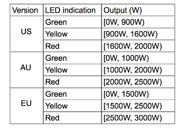
Its surface has a Smart RGB LED, which can be used for indicating the output load status or strength of the wireless signal. You can configure its indication colour according to your favour.
The Smart Switch 6 is also a security Z-wave device and supports Over The Air (OTA) feature for the products firmware upgrade.
Prepare for Installation / Reset
Please read the user manual before installing the product.
In order to include (add) a Z-Wave device to a network it must be in factory default state. Please make sure to reset the device into factory default. You can do this by performing an Exclusion operation as described below in the manual. Every Z-Wave controller is able to perform this operation however it is recommended to use the primary controller of the previous network to make sure the very device is excluded properly from this network.
Reset to factory default
This device also allows to be reset without any involvement of a Z-Wave controller. This procedure should only be used when the primary controller is inoperable.
Press and hold the Action button that you can find on the product"s housing for 20 seconds and then release.
Safety Warning for Mains Powered Devices
ATTENTION: only authorized technicians under consideration of the country-specific installation guidelines/norms may do works with mains power. Prior to the assembly of the product, the voltage network has to be switched off and ensured against re-switching.
Inclusion/Exclusion
On factory default the device does not belong to any Z-Wave network. The device needs to be added to an existing wireless network to communicate with the devices of this network. This process is called Inclusion.
Devices can also be removed from a network. This process is called Exclusion. Both processes are initiated by the primary controller of the Z-Wave network. This controller is turned into exclusion respective inclusion mode. Inclusion and Exclusion is then performed doing a special manual action right on the device.
Inclusion
Exclusion
Product Usage
Changing LED mode.
You can change the mode of how the LED acts through configuring Smart Switch. There are 3 different modes: Energy mode, Momentary indicate mode, and Night Light mode.
Energy mode will allow the LED to follow the state of Smart Switch, when the switch is on, the LED will be on, and while the switch is off, the current colour LED will be off and then remain the purple colour of 10% brightness. Momentary indicate mode will momentarily turn the LED on for 5 seconds then turn off after every state change in the switch. Night light mode will allow the LED to be turned on and off during your selected time of day you have configured for it.
Quick trouble shooting
Here are a few hints for network installation if things dont work as expected.
- Make sure a device is in factory reset state before including. In doubt exclude before include.
- If inclusion still fails, check if both devices use the same frequency.
- Remove all dead devices from associations. Otherwise you will see severe delays.
- Never use sleeping battery devices without a central controller.
- Dont poll FLIRS devices.
- Make sure to have enough mains powered device to benefit from the meshing
Firmware-Update over the Air
This device is capable of receiving a new firmware 'over the air'. The update function needs to be supported by the central controller. Once the controller starts the update process, perform the following action to confirm the firmware update: In the case that you need to firmware update your Smart Switch 6, please refer to this article here: https://aeotec.freshdesk.com/solution/articles/6000134294-smart-switch-6-firmware-v1-03-update
Association - one device controls an other device
Z-Wave devices control other Z-Wave devices. The relationship between one device controlling another device is called association. In order to control a different device, the controlling device needs to maintain a list of devices that will receive controlling commands. These lists are called association groups and they are always related to certain events (e.g. button pressed, sensor triggers, ...). In case the event happens all devices stored in the respective association group will receive the same wireless command wireless command, typically a 'Basic Set' Command.
Association Groups:
| Group Number | Maximum Nodes | Description |
|---|---|---|
| 1 | 5 | Group 1 is assigned to the Lifeline association group and every device has 5 nodes to associate.When the switch is turned on or off using the action button, the switch will send a basic report of its status to the nodes in association group 1. To change what kind of signal is sent to the nodes in group 1, please see the detailed description of configuration parameter 80. |
| 2 | 5 | When the product receives a controlling Basic Set CC/Switch Binary Set CC, which if cause the products load state to be changed, which will lead to send the Basic Set CC/Switch Binary Set CC to nodes in group 2. |
Configuration Parameters
Z-Wave products are supposed to work out of the box after inclusion, however certain configuration can adapt the function better to user needs or unlock further enhanced features.
IMPORTANT: Controllers may only allow configuring signed values. In order to set values in the range 128 ... 255 the value sent in the application shall be the desired value minus 256. For example: To set a parameter to 200 it may be needed to set a value of 200 minus 256 = minus 56. In case of a two byte value the same logic applies: Values greater than 32768 may needed to be given as negative values too.
Parameter 3: Current Overload Protection
This parameter is used for the overload protection, which means the load will be disconnected after 2 minutes when the current more than 14A. Size: 1 Byte, Default Value: 0
| Setting | Description |
|---|---|
| 0 | Overload Protection Disabled |
| 1 | Overload Protection is Enabled |
Parameter 20: Configure the output load status after re-power on
Configure the output load status after re-power on the Smart Switch. Size: 1 Byte, Default Value: 0
| Setting | Description |
|---|---|
| 0 | The output load status will be the same as the previous state before a power outage. |
| 1 | The output load status will be ON state after re-power on. |
| 2 | The output load status will be OFF state after re-power on. |
Parameter 33: Change the color value of RGB LED for testing
This parameter is only used for customer checking/testing the products RGB color via changing the RGB values. Size: 4 Byte, Default Value: 0
| Setting | Description |
|---|---|
| 0 - 255 | Reserved |
| 255 - 65535 | Range of red color value. |
| 65536 - 16777215 | Range of green color value. |
| 16777215 - 2147483647 | Range of blue color value. |
Parameter 80: Enable/Disable to send notifications to associated devices to associated devices.
This parameter is used to Enable/Disable to send notifications to associated devices (in Group 1) when the state of Smart Switch Gen5 load is changed. Size: 1 Byte, Default Value: 0
| Setting | Description |
|---|---|
| 0 | Send Nothing (Disabled) |
| 1 | Send HAIL Command |
| 2 | Send BASIC Report Command |
Parameter 81: Configure the state of LED
This parameter is used to configure the LED state when the Smart Switch is in Energy mode/Momentary indicate mode/Night light mode. Size: 1 Byte, Default Value: 0
| Setting | Description |
|---|---|
| 0 | The state of LED will follow with the output load state(Energy mode) |
| 1 | The state of LED will follow with the output load state, but will turn off after 5 seconds if there is no any switch action.(Momentary indicate mode) |
| 2 | The state of LED will the same with Night light mode state configured by parameter 83. |
Parameter 83: Configure the LED indication status when it is in Night light mode
This parameter is used to configure the LED indication status when the current mode is Night light mode. Size: 4 Byte, Default Value: 14524637
| Setting | Description |
|---|---|
| 0 - 255 | Set the indication value of red Led. |
| 256 - 65535 | Set the indication value of green Led. |
| 65536 - 16777215 | Set the indication value of blue Led. |
Parameter 84: Configure the brightness level for the LED indication
This parameter is used to configure the brightness level for the LED indication.Brightness level range is 0 to 100%. Size: 1 Byte, Default Value: 50
| Setting | Description |
|---|---|
| 0 - 100 | Brightness level range is 0 to 100%. |
Parameter 90: Enable/Disable the function of parameter 91 and 92.
This parameter is used to Enable/Disable the function of parameter 91 and 92. Size: 1 Byte, Default Value: 1
| Setting | Description |
|---|---|
| 0 | Configuration Parameters 91 and 92 are Disabled |
| 1 | Configuration Parameters 91 and 92 are Enabled |
Parameter 91: Induce an automatic report
This parameter is used to induce an automatic report when the change of the current power is more/less than the threshold in wattage. Size: 2 Byte, Default Value: 25
| Setting | Description |
|---|---|
| 0 - 32767 | The threshold can be set from 0 to 32767 watt. |
Parameter 92: Induce an automatic report
This parameter is used to induce an automatic report when the change of the current power is more/less than the threshold in percentage. Size: 1 Byte, Default Value: 5
| Setting | Description |
|---|---|
| 0 - 100 | The threshold can be set from 0 to 100 percent. |
Parameter 100: Reset Parameter 101 - 103
Size: 1 Byte, Default Value: 0
| Setting | Description |
|---|---|
| 1 | Reset Parameter 101-103 |
Parameter 101: To set which report need to be sent.
This parameter is used to configure which reports need to be sent in Report Group 1.The values corresponding to the first four bits of the parameter value may be combined to create different combinations of reports that you wish to have sent. For example, instantaneous Current is the value 2 and instantaneous Watts is the value 4, so setting parameter 101 to a value of 6 will result in both instantaneous Current and instantaneous Watts to be reported. See the full description of the parameter values for other possible settings. Size: 4 Byte, Default Value: 4
| Setting | Description |
|---|---|
| 1 | Report Instantaneous Voltage |
| 2 | Report Instantaneous Current (Amperes) |
| 4 | Report Instantaneous Watts |
| 8 | Report Accumulated kWh |
Parameter 102: To set which report need to be sent.
This parameter is used to configure which reports need to be sent in Report Group 2.The values corresponding to the first four bits of the parameter value may be combined to create different combinations of reports that you wish to have sent. For example, instantaneous Current is the value 2 and instantaneous Watts is the value 4, so setting parameter 102 to a value of 6 will result in both instantaneous Current and instantaneous Watts to be reported. See the full description of the parameter values for other possible settings. Size: 4 Byte, Default Value: 8
| Setting | Description |
|---|---|
| 1 | Report Instantaneous Voltage |
| 2 | Report Instantaneous Current (Amperes) |
| 4 | Report Instantaneous Watts |
| 8 | Report Accumulated kWh |
Parameter 103: To set which report need to be sent.
This parameter is used to configure which reports need to be sent in Report Group 3.The values corresponding to the first four bits of the parameter value may be combined to create different combinations of reports that you wish to have sent. For example, instantaneous Current is the value 2 and instantaneous Watts is the value 4, so setting parameter 103 to a value of 6 will result in both instantaneous Current and instantaneous Watts to be reported. See the full description of the parameter values for other possible settings. Size: 4 Byte, Default Value: 0
| Setting | Description |
|---|---|
| 1 | Report Instantaneous Voltage |
| 2 | Report Instantaneous Current (Amperes) |
| 4 | Report Instantaneous Watts |
| 8 | Report Accumulated kWh |
Parameter 110: Reset Parameter 111-113
Size: 1 Byte, Default Value: 0
| Setting | Description |
|---|---|
| 1 | Reset Parameter 111-113 |
Parameter 111: Set the interval time of sending report.
This parameter is used to set the interval time of sending report in Report Group 1. Size: 4 Byte, Default Value: 600
| Setting | Description |
|---|---|
| 0 - 268435456 | Interval Seconds |
Parameter 112: Set the interval time of sending report.
This parameter is used to set the interval time of sending report in Report Group 2. Size: 4 Byte, Default Value: 600
| Setting | Description |
|---|---|
| 0 - 268435456 | Interval Seconds |
Parameter 113: Set the interval time of sending report.
This parameter is used to set the interval time of sending report in Report Group 3. Size: 4 Byte, Default Value: 600
| Setting | Description |
|---|---|
| 0 - 268435456 | Interval Seconds |
Parameter 200: Partner ID
This parameter is used to configure the partner ID. Size: 1 Byte, Default Value: 0
| Setting | Description |
|---|---|
| 0 | Aeon Labs Standard Product |
| 1 - 255 | Partner ID of Partner Product |
Parameter 252: Enable/Disable Lock Configuration
This parameter is used to enable/disable Lock all configuration parameters. Size: 1 Byte, Default Value: 0
| Setting | Description |
|---|---|
| 0 | All configuration parameters are configurable. |
| 1 | All configuration parameters are not configurable (Locked). |
Parameter 254: Device Tag
This parameter is used to save the device tag, which will be written/ assigned in factory/ manufacturer. Size: 2 Byte, Default Value: 0
| Setting | Description |
|---|---|
| 0 - 32767 | Device Tag |
Parameter 255: Reset to default factory setting
This parameter is used to reset product to default factory setting. (There are just 2 values can be used). Size: 4 Byte, Default Value: 0
| Setting | Description |
|---|---|
| 1 | Resets all configuration parameters to default setting. |
| 1431655765 | Reset the product to default factory setting and be excluded from the Z-wave network. |
Technical Data
| Dimensions | 58x58x70 mm |
| Weight | 121 gr |
| Hardware Platform | ZM5101 |
| EAN | 1220000013049 |
| IP Class | IP 20 |
| Voltage | 230 V |
| Load | 3000 W |
| Device Type | On/Off Power Switch |
| Network Operation | Always On Slave |
| Z-Wave Version | 6.51.06 |
| Certification ID | ZC10-15080004 |
| Z-Wave Product Id | 0x0086.0x0003.0x0060 |
| Frequency | Europe - 868,4 Mhz |
| Maximum transmission power | 5 mW |
Supported Command Classes
- Switch All
- Association
- Association Group Information
- Basic
- Clock
- Configuration
- Device Reset Locally
- Firmware Update Md
- Manufacturer Specific
- Meter
- Powerlevel
- Security
- Switch Binary
- Version
- Zwaveplus Info
Controlled Command Classes
- Basic
- Hail
- Switch Binary
Explanation of Z-Wave specific terms
- Controller — is a Z-Wave device with capabilities to manage the network. Controllers are typically Gateways,Remote Controls or battery operated wall controllers.
- Slave — is a Z-Wave device without capabilities to manage the network. Slaves can be sensors, actuators and even remote controls.
- Primary Controller — is the central organizer of the network. It must be a controller. There can be only one primary controller in a Z-Wave network.
- Inclusion — is the process of adding new Z-Wave devices into a network.
- Exclusion — is the process of removing Z-Wave devices from the network.
- Association — is a control relationship between a controlling device and a controlled device.
- Wakeup Notification — is a special wireless message issued by a Z-Wave device to announces that is able to communicate.
- Node Information Frame — is a special wireless message issued by a Z-Wave device to announce its capabilities and functions.