Aeotec
Single Nano Switch with measuring
SKU: AEOEZW116

Quickstart
This is a
1. Install the device according to the instructions.
2. Press the button 2 times quickly on the Nano Switch.
Important safety information
Please read this manual carefully. Failure to follow the recommendations in this manual may be dangerous or may violate the law. The manufacturer, importer, distributor and seller shall not be liable for any loss or damage resulting from failure to comply with the instructions in this manual or any other material. Use this equipment only for its intended purpose. Follow the disposal instructions. Do not dispose of electronic equipment or batteries in a fire or near open heat sources.Product Description
It can connect to 2 external manual switches to control the load ON/OFF independently. Its surface has a pin socket, which can be used for connecting to the touch panel, so you can also use the touch panel to control the Nano Switch.
The Nano Switch is also a security Z-Wave device and supports Over The Air (OTA) feature for the products firmware upgrade.
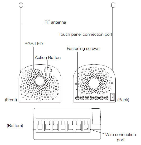
Installation
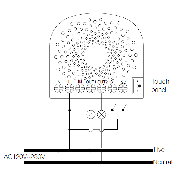
Notes for the wire connection ports:
Note: All connection wires needs to be flexible cable.
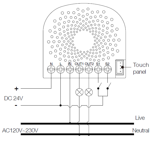
Wiring diagram of AC120V/230V power input.
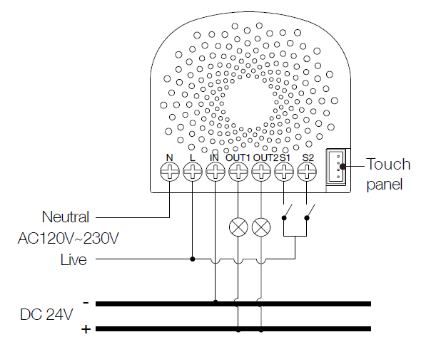 Note: The ?IN? terminal should be connected to the ?-? of DC 24V input.
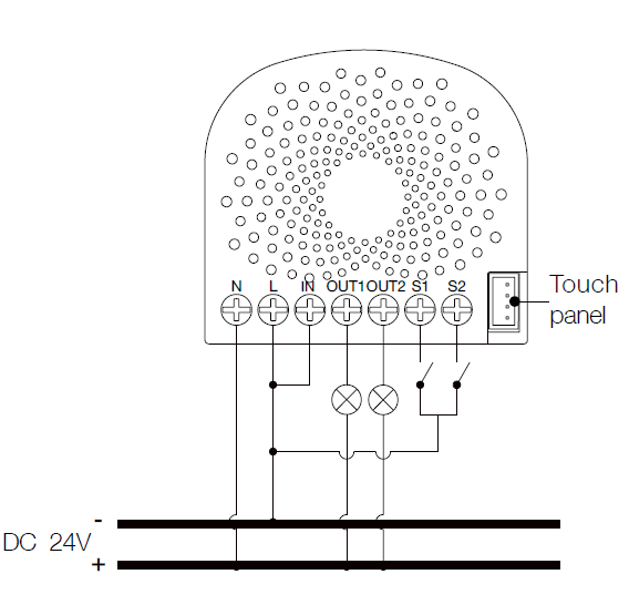
| Reset to factory default | Set Parameter 255 |
| Inclusion | 1. Install the device according to the instructions. 2. Press the button 2 times quickly on the Nano Switch. |
| Exclusion | 1. Press the button once on the Dual Nano Switch. |
| NIF | XXXNIF |
| Wakeup | XXXWakeupDescription |
| Protection | XXXProtection |
| FirmwareUpdate | XXXFirmwareUpdate |
| SetAssociation | XXXSetAssociation |
Association Groups:
| Group Number | Maximum Nodes | Description |
|---|---|---|
| 1 | 5 | Z-Wave Plus Lifeline.When the load state of Nano Switch (on/off) is changed, the Hail CC, Switch Multilevel Report and Basic Report (configured by parameter 80) can be sent to the associated nodes in this group. |
| 2 | 5 | Forward the Basic Set, Switch All, Scene Activation Set to associated nodes in Group 2 when the Nano Switch receives the Basic Set, Switch All, Scene Activation Set commands from main controller. |
| 3 | 5 | Send Basic Set (configured by parameter 82) to the associated nodes in Group 3 when the external switch S1 is operated |
| 4 | 5 | Send Basic Set (configured by parameter 82) to the associated nodes in Group 4 when the external switch S2 is operated |
Configuration Parameters
Parameter 3: Current Overload Protection.
Over current protection. Output load will be closed after 30 seconds if the current exceeds (US: 15.5A, AU or EU: 10.5A) Size: 1 Byte, Default Value: 1
| Setting | Description |
|---|---|
| 0 | Disable |
| 1 | Enable |
Parameter 4: Overheat protection.
Output Load will be turned off automatically after 30 seconds and if the temperature of product inside exceeds 100°C. Size: 1 Byte, Default Value: 0
| Setting | Description |
|---|---|
| 0 | Disable |
| 1 | Enable |
Parameter 20: Configure the output status after re-power on it.
Configure the output status after re-power on it. Size: 1 Byte, Default Value: 0
| Setting | Description |
|---|---|
| 0 | Last status |
| 1 | Always on |
| 2 | Always off |
Parameter 80: To set which notification would be sent to the associated devices (Group 1)
To set which notification would be sent to the associated devices (Group 1) when the state of Nano Dimmers load is changed. Size: 1 Byte, Default Value: 0
| Setting | Description |
|---|---|
| 0 | Send Nothing |
| 1 | Send Hail CC |
| 2 | Send Basic CC report |
| 3 | Send Multilevel Switch report |
| 4 | Send Hail CC when using the manual switch to change the load state. |
Parameter 81: To set which notification would be sent to the associated nodes in association group 3
To set which notification would be sent to the associated nodes in association Group 3 when using the external switch 1 to switch the loads. Size: 1 Byte, Default Value: 1
| Setting | Description |
|---|---|
| 0 | Send Nothing |
| 1 | Send Basic Set CC |
Parameter 82: To set which notification would be sent to the associated nodes in association group 4
To set which notification would be sent to the associated nodes in association Group 4 when using the external switch 2 to switch the loads. Size: 1 Byte, Default Value: 1
| Setting | Description |
|---|---|
| 0 | Send Nothing |
| 1 | Send Basic Set CC |
Parameter 83: Configure the state of LED
Configure the state of LED when it is in 3 modes Size: 1 Byte, Default Value: 0
| Setting | Description |
|---|---|
| 0 | The LED will follow the status (on/off) of its load (Energy mode). |
| 256 - 316 | The hour value of ON time |
| 2 | Night light mode. |
Parameter 84: ON/OFF time
Set the ON/OFF time of the LED when it is in Night light mode. Size: 4 Byte, Default Value: 524306
| Setting | Description |
|---|---|
| 0 - 60 | The minute time of OFF |
| 256 - 316 | The hour time of OFF |
| 65536 - 65596 | The minute time of ON |
| 16777216 - 16777276 | The hour time of ON |
Parameter 86: Set appointment 1
Set appointment 1 Size: 4 Byte, Default Value: 2293760
| Setting | Description |
|---|---|
| 0 - 60 | The minute value of ON time |
| 256 - 316 | The minute value of ON time |
| 65536 - 65543 | The day value (Mon to Sun) |
| 16777215 | Disable the setting. |
| 16777216 | Enable the setting. |
Parameter 87: Set appointment 2
Set appointment 2 Size: 4 Byte, Default Value: 2293760
| Setting | Description |
|---|---|
| 0 - 60 | The minute value of ON time |
| 256 - 316 | The hour value of ON time |
| 65536 - 65543 | The day value (Mon to Sun) |
| 16777215 | Disable the setting. |
| 16777216 | Enable the setting. |
Parameter 90: Enables/disables parameter 91 and 92 below:
Enables/disables the function of parameter 91 and 92. Size: 1 Byte, Default Value: 0
| Setting | Description |
|---|---|
| 0 | Disable |
| 1 | Enable |
Parameter 91: Set the threshold value of wattage.
Threshold change in wattage (in terms of wattage) to induce an automatic report. Size: 2 Byte, Default Value: 25
| Setting | Description |
|---|---|
| 0 - 60000 | The thershold value range is 0 to 60000 |
Parameter 92: Set the threshold value of wattage.
Threshold change in wattage (in terms of percentage) to induce an automatic report. Size: 1 Byte, Default Value: 5
| Setting | Description |
|---|---|
| 0 - 100 | The thershold value range is 0 to 100 |
Parameter 100: Set parameter 101-103 to default value.
Set parameter 101-103 to default value. Size: 1 Byte, Default Value: 0
| Setting | Description |
|---|---|
| 0 | Reset the parameter 101-103 |
Parameter 101: To set which reports need to be sent in Report group 1.
To set which reports need to be sent in Report group 1. Size: 4 Byte, Default Value: 0
| Setting | Description |
|---|---|
| 1 | Send Meter Report of voltage (V) |
| 2 | Send Meter Report of current (A) |
| 4 | Send Meter Report of wattage (W) |
| 8 | Send Meter Report of energy (kWh) |
Parameter 102: To set which reports need to be sent in Report group 2.
To set which reports need to be sent in Report group 2. Size: 1 Byte, Default Value: 0
| Setting | Description |
|---|---|
| 1 | Send Meter Report of voltage (V) |
| 2 | Send Meter Report of current (A) |
| 4 | Send Meter Report of wattage (W) |
| 8 | Send Meter Report of energy (kWh) |
Parameter 103: To set which reports need to be sent in Report group 3.
To set which reports need to be sent in Report group 3. Size: 1 Byte, Default Value: 0
| Setting | Description |
|---|---|
| 1 | Send Meter Report of voltage (V) |
| 2 | Send Meter Report of current (A) |
| 4 | Send Meter Report of wattage (W) |
| 8 | Send Meter Report of energy (kWh) |
Parameter 110: Set parameter 111-113 to default value.
Set parameter 111-113 to default value. Size: 1 Byte, Default Value: 0
| Setting | Description |
|---|---|
| 0 | Reset the parameter 111-113 |
Parameter 111: Set the interval of automatic report for Report group 1.
Set the interval of automatic report for Report group 1. Size: 4 Byte, Default Value: 3
| Setting | Description |
|---|---|
| 1 - 2147483647 | The range of interval time is 1 to 2147483647. |
Parameter 112: Set the interval of automatic report for Report group 2.
Set the interval of automatic report for Report group 2. Size: 4 Byte, Default Value: 600
| Setting | Description |
|---|---|
| 1 - 2147483647 | The range of interval time is 1 to 2147483647. |
Parameter 113: Set the interval of automatic report for Report group 2.
Set the interval of automatic report for Report group 3. Size: 4 Byte, Default Value: 600
| Setting | Description |
|---|---|
| 1 - 2147483647 | The range of interval time is 1 to 2147483647. |
Parameter 120: Configure the external switch mode for S1.
Configure the external switch mode for S1. Size: 1 Byte, Default Value: 0
| Setting | Description |
|---|---|
| 0 | Enter automatic identification mode |
| 1 | Momentary push button mode |
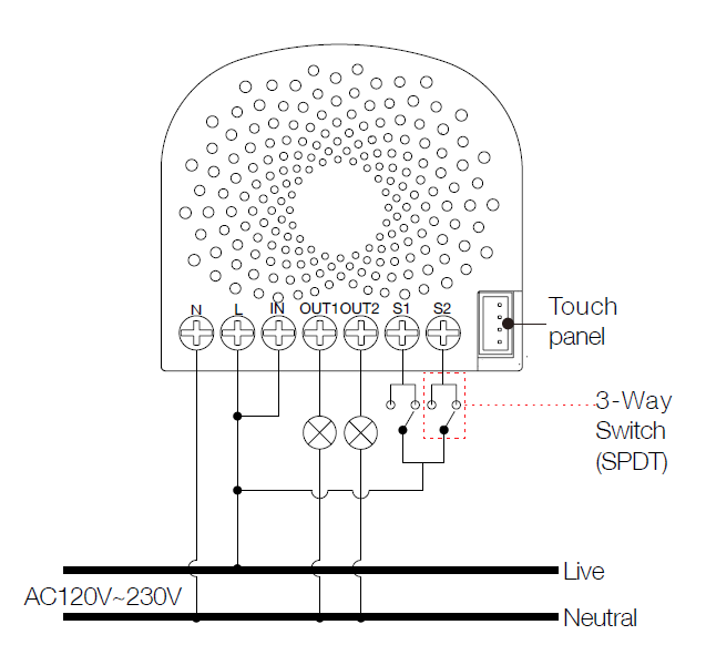
| 2 | 3 way switch mode |
| 3 | 2-state switch mode |
Parameter 121: Configure the external switch mode for S2.
Configure the external switch mode for S2. Size: 1 Byte, Default Value: 0
| Setting | Description |
|---|---|
| 0 | Enter automatic identification mode |
| 1 | Momentary push button mode |
| 2 | 3 way switch mode |
| 3 | 2-state switch mode |
Parameter 122: Set the control destination for external switch S1
Set the control destination of the external switch. Size: 1 Byte, Default Value: 3
| Setting | Description |
|---|---|
| 1 | control the output loads of itself. |
| 2 | control the other nodes |
| 3 | control the output loads of itself and other nodes. |
Parameter 252: Lock/unlock configuration parameters
Lock/unlock configuration parameters. Size: 1 Byte, Default Value: 0
| Setting | Description |
|---|---|
| 0 | Unlock |
| 1 | Lock |
Parameter 255: Reset the Nano Dimmer
Reset the Nano Dimmer to factory default. Size: 4 Byte, Default Value: 0
| Setting | Description |
|---|---|
| 0 | Reset all configuration parameters to factory default setting |
| 1431655765 | Reset to factory default setting and removed from the z-wave network |
Technical Data
| Dimensions | 0.0425000x0.0400000x0.0200000 mm |
| Weight | 28.5 gr |
| Hardware Platform | ZM5202 |
| EAN | 1220000015333 |
| IP Class | IP 20 |
| Voltage | 24V DC/ 230V AC |
| Load | 10 A |
| Device Type | On/Off Power Switch |
| Generic Device Class | Binary Switch |
| Specific Device Class | Binary Power Switch |
| Firmware Version | 01.00 |
| Z-Wave Version | 04.22 |
| Certification ID | ZC10-17035496 |
| Z-Wave Product Id | 0x0086.0x0003.0x0074 |
| Frequency | Europe - 868,4 Mhz |
| Maximum transmission power | 5 mW |