Aeotec
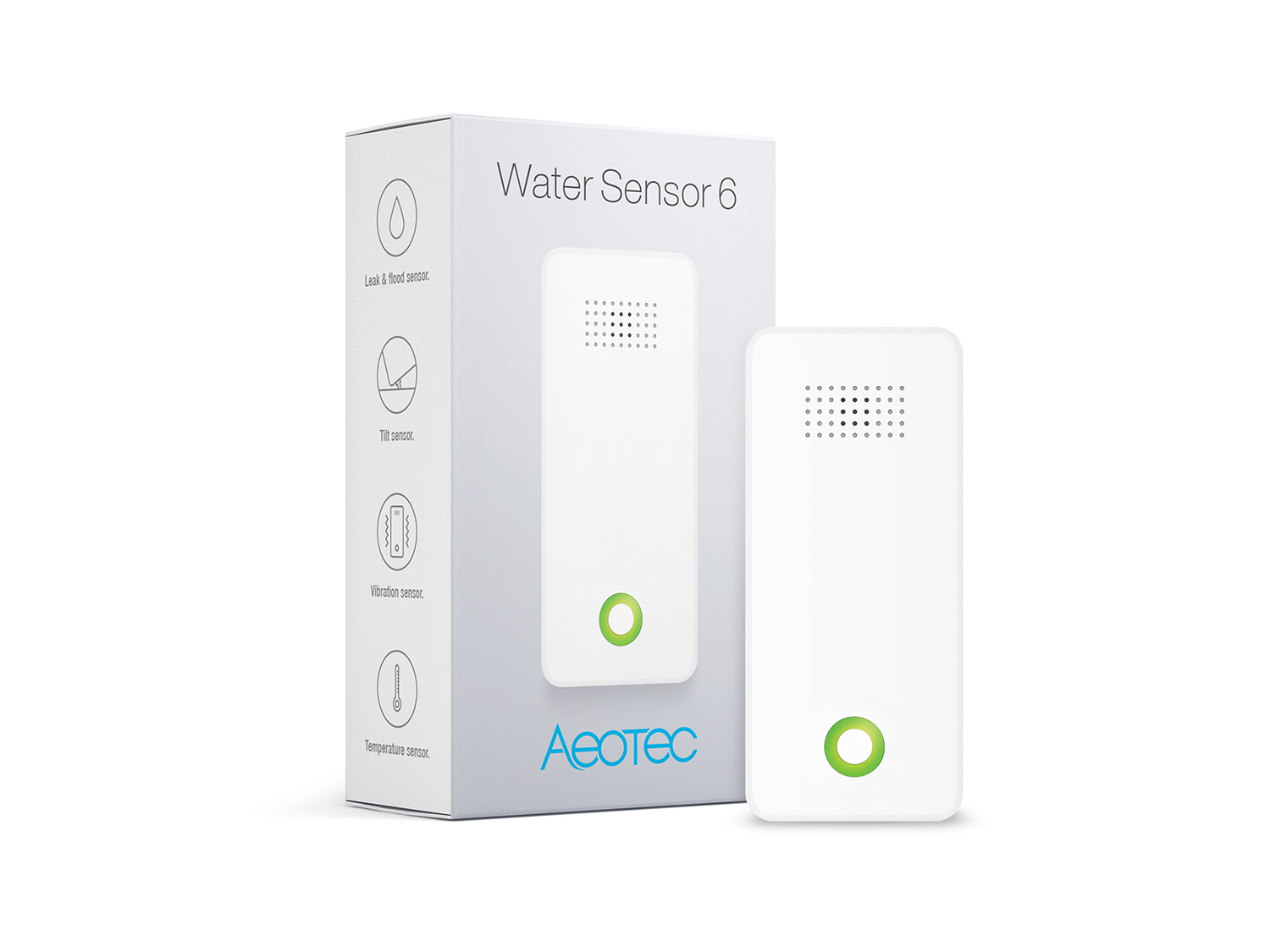
Water Sensor 6
SKU: AEOEZW122


Quickstart
This is a
Turn the primary controller of Z-Wave network into inclusion mode, short press the products Action Button that you can find on the product.
Important safety information
Please read this manual carefully. Failure to follow the recommendations in this manual may be dangerous or may violate the law. The manufacturer, importer, distributor and seller shall not be liable for any loss or damage resulting from failure to comply with the instructions in this manual or any other material. Use this equipment only for its intended purpose. Follow the disposal instructions. Do not dispose of electronic equipment or batteries in a fire or near open heat sources.What is Z-Wave?
Z-Wave is the international wireless protocol for communication in the Smart Home. This device is suited for use in the region mentioned in the Quickstart section.
Z-Wave ensures a reliable communication by reconfirming every message (two-way communication) and every mains powered node can act as a repeater for other nodes (meshed network) in case the receiver is not in direct wireless range of the transmitter.
This device and every other certified Z-Wave device can be used together with any other certified Z-Wave device regardless of brand and origin as long as both are suited for the same frequency range.
If a device supports secure communication it will communicate with other devices secure as long as this device provides the same or a higher level of security. Otherwise it will automatically turn into a lower level of security to maintain backward compatibility.
For more information about Z-Wave technology, devices, white papers etc. please refer to www.z-wave.info.
Product Description
Aeotec by Aeon Labs Water Sensor 6 brings intelligence to a new level, one that is suited to both safety and convenience. It contains 4 sensing points, which would be more accurately to detect the presence and absence of water or detect whether there is water leak in some places of your home. The Water Sensor 6 has an inbuilt buzzer that can play alarm sounds to let you know when the water is detected. The Water Sensor 6 is also a security Z-Wave device that supports Over The Air (OTA) for firmware updates.
Prepare for Installation / Reset
Please read the user manual before installing the product.
In order to include (add) a Z-Wave device to a network it must be in factory default state. Please make sure to reset the device into factory default. You can do this by performing an Exclusion operation as described below in the manual. Every Z-Wave controller is able to perform this operation however it is recommended to use the primary controller of the previous network to make sure the very device is excluded properly from this network.
Reset to factory default
This device also allows to be reset without any involvement of a Z-Wave controller. This procedure should only be used when the primary controller is inoperable.
- Press and hold the Action Button of your Water Sensor 6 for 20 seconds.
- Wait until the RGB LED turns into a green or rainbow gradient Color after 20 seconds of holding.
- Release the Action Button.
- If your Water Sensor 6 has been successfully factory reset, the RGB LED will be active with a colorful gradient for 3 seconds before disappearing. When you tap the Action Button on Water Sensor, its green LED will blink rapidly. If the factory reset was unsuccessful, the green LED will remain on solid for a few seconds when you tap the Action Button.
Safety Warning for Batteries
The product contains batteries. Please remove the batteries when the device is not used. Do not mix batteries of different charging level or different brands.
Inclusion/Exclusion
On factory default the device does not belong to any Z-Wave network. The device needs to be added to an existing wireless network to communicate with the devices of this network. This process is called Inclusion.
Devices can also be removed from a network. This process is called Exclusion. Both processes are initiated by the primary controller of the Z-Wave network. This controller is turned into exclusion respective inclusion mode. Inclusion and Exclusion is then performed doing a special manual action right on the device.
Inclusion
Exclusion
Product Usage
Optimally placing Water Sensor 6.
The final installation steps of Water Sensor 6 are very simple, all you need to do is choose the area that you want Water Sensor 6 to monitor leaks or floods in.
Water Sensor 6 is optimally placed on a flat surface where floods, leaks and drips can occur; these can include your washroom or kitchen. When placing it, ensure that its detection probes touch the surface being monitored; when water touches any 2 of the 4 probes on Water Sensor 6 an alert will be sent to your Z-Wave network. Below are some of the possible situations that can trigger Water Sensor 6.
1. Water is detected by sensing point 2 and 4.
2. Water is detected by sensing point 1 and 3.,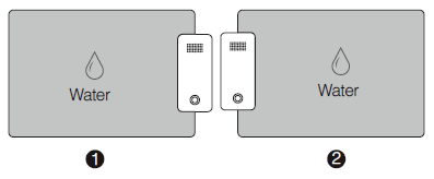
3. Water is detected by sensing point 1 and 2.
4. Water is detected by sensing point 3 and 4.
5. Water is detected by sensing point 1, 2, 3 and 4.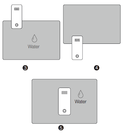
These situations will cause Water Sensor 6 to send a water presence or trigger event to your gateway. Should water clear from the area where Water Sensor 6 is installed, the sensor will also send a separate command to your Z-Wave gateway informing it that there is no more water in the area.
Testing Health Connectivity.
Note - Health test does not test for routing communication health, only tests for direct communication with your gateway to determine if it has a healthy direct connection.
You can determine the health of your Water Sensor 6s connectivity to your gateway using a manual button press, hold, and release function which is indicated by the LED color.
1. Press and hold Water Sensor 6 Action button
2. Wait until the RGB LED turns into a Purple Color
3. Release Water Sensor 6 Action Button
The RGB LED will blink its Purple color while sending ping messages to your gateway, when it has finished, it will blink 1 of 3 colors:
Red = Bad HealthYellow = Moderate Health
Yellow = Moderate Health
Green = Great Health
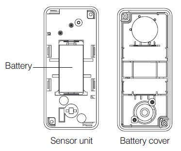
Replacing your sensors battery.
Your Water Sensor 6 uses 1x CR123A battery that has a 2 year battery life maximum. Ultimately the battery life of the sensor will highly depend on the uses and settings of Water Sensor. When battery power has depleted, below are the steps you can take to replace the battery in your Water Sensor 6.
1. Unscrew the 2 screws from Water Sensor 6. On the rear of Water Sensor 6 you‘ll find 2 screws in opposing corners.
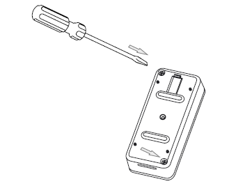
2. Separate the battery cover from the Sensor unit. Use the separation tool to separate the battery cover by pushing or moving the separation along the gap between the battery cover and the sensor unit. 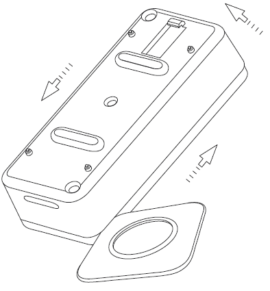
a. Pull open a small gap between the battery cover and Sensor unit.
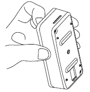
b. Push or move your fingernail along the gap between the battery cover and Sensor unit.
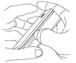
3. Once the battery cover is separated from the Sensor Unit, you can pull out and change the battery located in the center of the Water Sensor 6 hardware.
Node Information Frame
The Node Information Frame (NIF) is the business card of a Z-Wave device. It contains information about the device type and the technical capabilities. The inclusion and exclusion of the device is confirmed by sending out a Node Information Frame. Beside this it may be needed for certain network operations to send out a Node Information Frame. To issue a NIF execute the following action: Press the Z-Wave Button
Communication to a Sleeping device (Wakeup)
This device is battery operated and turned into deep sleep state most of the time to save battery life time. Communication with the device is limited. In order to communicate with the device, a static controller C is needed in the network. This controller will maintain a mailbox for the battery operated devices and store commands that can not be received during deep sleep state. Without such a controller, communication may become impossible and/or the battery life time is significantly decreased.
This device will wakeup regularly and announce the wakeup state by sending out a so called Wakeup Notification. The controller can then empty the mailbox. Therefore, the device needs to be configured with the desired wakeup interval and the node ID of the controller. If the device was included by a static controller this controller will usually perform all necessary configurations. The wakeup interval is a tradeoff between maximal battery life time and the desired responses of the device. To wakeup the device please perform the following action: Pressing the Action Button once will trigger sending the Wake up notification command. If press and hold the Z-Wave button for 3 seconds, the Water Sensor will wake up for 10 minutes.
Quick trouble shooting
Here are a few hints for network installation if things dont work as expected.
- Make sure a device is in factory reset state before including. In doubt exclude before include.
- If inclusion still fails, check if both devices use the same frequency.
- Remove all dead devices from associations. Otherwise you will see severe delays.
- Never use sleeping battery devices without a central controller.
- Dont poll FLIRS devices.
- Make sure to have enough mains powered device to benefit from the meshing
Association - one device controls an other device
Z-Wave devices control other Z-Wave devices. The relationship between one device controlling another device is called association. In order to control a different device, the controlling device needs to maintain a list of devices that will receive controlling commands. These lists are called association groups and they are always related to certain events (e.g. button pressed, sensor triggers, ...). In case the event happens all devices stored in the respective association group will receive the same wireless command wireless command, typically a 'Basic Set' Command.
Association Groups:
| Group Number | Maximum Nodes | Description |
|---|---|---|
| 1 | 5 | Lifeline group.1. The Battery Report or Multilevel Sensor Report (Configurable) can be sent to the associated nodes in group 1.2. When the water leak is detected, the Notification Report will be send to the associated nodes in group 1.3. When the Water Sensor is reset, the Device Reset Locally CC will be send to the associated nodes in group 1. |
| 2 | 5 | Send the configuration parameter 136 (0x88) to the associated nodes in group 2. |
| 3 | 5 | Send Basic Set (configured by parameter 88 (0x58) to the associated nodes in Group 3 when the Sensor probe 1 is triggered. |
| 4 | 5 | Send Basic Set (configured by parameter 89 (0x59) to the associated nodes in Group 4 when the Sensor probe 2 is triggered. |
Configuration Parameters
Z-Wave products are supposed to work out of the box after inclusion, however certain configuration can adapt the function better to user needs or unlock further enhanced features.
IMPORTANT: Controllers may only allow configuring signed values. In order to set values in the range 128 ... 255 the value sent in the application shall be the desired value minus 256. For example: To set a parameter to 200 it may be needed to set a value of 200 minus 256 = minus 56. In case of a two byte value the same logic applies: Values greater than 32768 may needed to be given as negative values too.
Parameter 2: Enable/Disable waking up for 10 minutes when re-power on (battery mode) the MultiSensor.
Enable/Disable waking up for 10 minutes when re-power on (battery mode) the MultiSensor. Size: 1 Byte, Default Value: 0
| Setting | Description |
|---|---|
| 0 | Disable |
| 1 | Enable. |
Parameter 8: Set the timeout of awake after the Wake Up CC is sent out..
Set the timeout of awake after the Wake Up CC is sent out.. Size: 1 Byte, Default Value: 30
| Setting | Description |
|---|---|
| 8 - 127 | Available rang is 8 to 127 seconds. |
Parameter 9: Report the current power mode and the product state for battery power mode
Report the current power mode and the product state for battery power mode.Note: this parameter cannot be used as Set usage. Size: 2 Byte, Default Value: 0
| Setting | Description |
|---|---|
| 0 | USB power mode |
| 256 | Keep sleep state for Battery power mode |
| 257 | Keep awake for 10 minutes for battery power mode. |
Parameter 10: Set the alarm time for the Buzzer when the sensor is triggered.
Set the alarm time for the Buzzer when the sensor is triggered. Size: 4 Byte, Default Value: 101968650
| Setting | Description |
|---|---|
| 1 - 255 | Repeated cycle of Buzzer alarm. |
| 256 - 65535 | the time of Buzzer keeping ON state (MSB) |
| 65536 - 2147483647 | The time of Buzzer keeping OFF state |
Parameter 39: Configure the default low battery value.
Configure the default low battery value. When the current battery level is lower than this value, it will send out the low battery alarm. Size: 1 Byte, Default Value: 20
| Setting | Description |
|---|---|
| 10 - 50 | Available rang is 10% to 50%. |
Parameter 48: Enable/disable the sensor report
Enable/disable the sensor report Size: 1 Byte, Default Value: 0
| Setting | Description |
|---|---|
| 0 | Disable |
| 1 | Notification Report for Water Leak event |
| 2 | Notification Report for Vibration event |
| 4 | Configuration Report for Tilt sensor |
| 16 | Notification Report for Under heat alarm |
| 32 | Notification Report for Overheat alarm |
Parameter 49: Set the upper limit value (overheat).
Set the upper limit value (overheat). Size: 4 Byte, Default Value: 68157696
| Setting | Description |
|---|---|
| 0 | Celsius unit |
| 1 | Fahrenheit unit |
| 65536 - 2147483647 | Temperature value |
Parameter 50: Set the lower limit value (under heat)
Set the lower limit value (under heat) Size: 4 Byte, Default Value: 20971776
| Setting | Description |
|---|---|
| 0 | Celsius unit |
| 1 | Fahrenheit unit |
| 65536 - 2147483647 | Temperature value |
Parameter 57: Set the recover limit value of temperature sensor.
Note:1. When the current measurement <= (Upper limit - Recover limit), the upper limit report is enabled and then it would send out a sensor report when the next measurement is more than the upper limit. After that the upper limit report would be disabled again until the measurement <= (Upper limit - Recover limit).2. When the current measurement >= (Lower limit + Recover limit), the lower limit report is enabled and then it would send out a sensor report when the next measurement is less than the lower limit. After that the lower limit report would be disabled again until the measurement >= (Lower limit + Recover limit).3. High byte is the recover limit value. Low byte is the unit (0x01=Celsius, 0x02=Fahrenheit). Size: 2 Byte, Default Value: 5121
| Setting | Description |
|---|---|
| 10 - 255 | Available rang is 1.0°C to 25.5°C |
Parameter 64: Set the default unit of the automatic temperature report in parameter 101-103.
Set the default unit of the automatic temperature report in parameter 101-103. Size: 1 Byte, Default Value: 1
| Setting | Description |
|---|---|
| 0 | The unit is Celsius. |
| 1 | The unit is Fahrenheit. |
Parameter 84: Get the state of tilt sensor
Get the state of tilt sensor.Note: this is a Get-only parameter. Size: 1 Byte, Default Value: 0
| Setting | Description |
|---|---|
| 0 | The Water Sensor main unit is in horizontal direction. |
| 1 | The Water Sensor main unit is in vertical direction. |
Parameter 86: Enable/ disable the buzzer.
Enable/ disable the buzzer. Size: 1 Byte, Default Value: 1
| Setting | Description |
|---|---|
| 0 | Disable |
| 1 | Enable |
Parameter 87: To set which sensor is triggered the buzzer will alarm.
To set which sensor is triggered the buzzer will alarm. Size: 4 Byte, Default Value: 55
| Setting | Description |
|---|---|
| 1 | If the Water leak is triggered, the buzzer will alarm. |
| 2 | If the vibration is triggered, the buzzer will alarm. |
| 4 | If the tilt sensor is triggered, the buzzer will alarm. |
| 16 | If the under heat is triggered, the buzzer will alarm |
| 32 | If the overheat is triggered, the buzzer will alarm. |
Parameter 88: To set which value of the Basic Set will be sent to the associated nodes in association Group 3 when the Sensor probe 1 is triggered.
To set which value of the Basic Set will be sent to the associated nodes in association Group 3 when the Sensor probe 1 is triggered. Size: 1 Byte, Default Value: 0
| Setting | Description |
|---|---|
| 0 | Send nothing |
| 1 | Presence of water, send Basic Set 255 (0xFF), absence of water, send Basic Set 0 (0x00). |
| 2 | Presence of water, send Basic Set 0 (0x00), absence of water, send Basic Set 255 (0xFF). |
Parameter 89: To set which value of the Basic Set will be sent to the associated nodes in association Group 4 when the Sensor probe 2 is triggered.
To set which value of the Basic Set will be sent to the associated nodes in association Group 4 when the Sensor probe 2 is triggered. Size: 1 Byte, Default Value: 0
| Setting | Description |
|---|---|
| 0 | Send nothing. |
| 1 | Presence of water, send Basic Set 255 (0xFF), absence of water, send Basic Set = 0 (0x00). |
| 2 | Presence of water, send Basic Set 0 (0x00), absence of water, send Basic Set 255 (0xFF). |
Parameter 94: To set which power source level is reported via the Battery CC.
To set which power source level is reported via the Battery CC. Size: 1 Byte, Default Value: 0
| Setting | Description |
|---|---|
| 0 | report the USB power level. |
| 1 | report the CR123A battery level. |
Parameter 101: To set what unsolicited report would be sent to the Lifeline group.
To set what unsolicited report would be sent to the Lifeline group. Size: 1 Byte, Default Value: 3
| Setting | Description |
|---|---|
| 0 | Send Nothing |
| 1 | Battery Report is enabled. |
| 2 | Multilevel sensor report for temperature is enabled. |
| 3 | Battery Report and Multilevel sensor report for temperature are enabled. |
Parameter 111: To set the interval time of sending reports in Report group 1
To set the interval time of sending reports in Report group 1.Note:1. The unit of interval time is second if USB power.2. If battery power, the minimum interval time is equal to Wake Up interval set by the Wake Up CC. Size: 4 Byte, Default Value: 3600
| Setting | Description |
|---|---|
| 5 - 2678400 | Available rang is 5 to 2678400 seconds. |
Parameter 135: To set which sensor report can be sent when the water leak event is triggered and if the receiving device is a non-multichannel device.
To set which sensor report can be sent when the water leak event is triggered and if the receiving device is a non-multichannel device. Size: 1 Byte, Default Value: 1
| Setting | Description |
|---|---|
| 0 | Send nothing |
| 1 | Send notification report to association group 1. |
| 2 | Send configuration 136 (0x88) report to association group 2. |
| 3 | Send notification report to association group 1 and Send configuration 136 (0x88) report to association group 2. |
Parameter 136: When the parameter 135 (0x87) is set to 2 or 3, it can get the sensor probes status through this configuration value.
When the parameter 135 (0x87) is set to 2 or 3, it can get the sensor probes status through this configuration value.Note: This parameter is a Get- only parameter. Size: 1 Byte, Default Value: 0
| Setting | Description |
|---|---|
| 0 | absence of water is triggered by probe 1. |
| 1 | presence of water is triggered by probe 1. |
| 2 | presence of water is triggered by probe 2. |
Parameter 201: Temperature sensor calibration
Temperature sensor calibration.Note:1. High byte is the calibration value. Low byte is the unit (0 (0x00)=Celsius, 1 (0x01)=Fahrenheit)2. The calibration value (high byte) contains one decimal point. E.g. if the value is set to 20 (0x1400), the calibration value is 2.0 °C (EU/AU version) or if the value is set to 20 (0x1401), the calibration value is 2.0 °F(US version) 3. The calibration value (high byte) = standard value - measure value.E.g. If measure value =25.3°C and the standard value = 23.2°C, so the calibration value= 23.2°C - 25.3°C= -2.1°C (0xEB).If the measure value =30.1°C and the standard value = 33.2°C, so the calibration value= 33.2°C - 30.1°C=3.1°C (0x1F). Size: 2 Byte, Default Value: 1
| Setting | Description |
|---|---|
| -128 - 127 | Available rang is -12.8°C to 12.7°C. |
Parameter 252: Enable/disable all configuration parameters to be locked
Enable/disable all configuration parameters to be locked. Size: 1 Byte, Default Value: 0
| Setting | Description |
|---|---|
| 0 | Disable |
| 1 | Enable. |
Parameter 255: Reset to factory defaults.
Reset to factory defaults. Size: 4 Byte, Default Value: 0
| Setting | Description |
|---|---|
| 1 | Reset all configuration parameters to factory defaults. |
| 1431655765 | Reset the product to factory defaults. |
Technical Data
| Dimensions | 0.0380000x0.0850000x0.0240000 mm |
| Weight | 62 gr |
| Hardware Platform | ZM5101 |
| EAN | 1220000015258 |
| IP Class | IP 65 |
| Battery Type | 1 * CR123A |
| Device Type | Notification Sensor |
| Network Operation | Reporting Sleeping Slave |
| Z-Wave Version | 6.51.09 |
| Certification ID | ZC10-17055615 |
| Z-Wave Product Id | 0x0086.0x0002.0x007A |
| Firmware Updatable | Updatable by Consumer by RF |
| IP (Ingress Protection) Rated | ok |
| Sensors | Air TemperatureWater Flow |
| Supported Notification Types | Heat AlarmHome SecurityWater Alarm |
| Frequency | Europe - 868,4 Mhz |
| Maximum transmission power | 5 mW |
Supported Command Classes
- Association Grp Info
- Association V2
- Battery
- Configuration
- Device Reset Locally
- Firmware Update Md V2
- Manufacturer Specific V2
- Multi Channel V4
- Multi Channel Association V2
- Notification V4
- Powerlevel
- Security
- Sensor Multilevel V5
- Version V2
- Wake Up V2
- Zwaveplus Info V2
Controlled Command Classes
- Basic
Explanation of Z-Wave specific terms
- Controller — is a Z-Wave device with capabilities to manage the network. Controllers are typically Gateways,Remote Controls or battery operated wall controllers.
- Slave — is a Z-Wave device without capabilities to manage the network. Slaves can be sensors, actuators and even remote controls.
- Primary Controller — is the central organizer of the network. It must be a controller. There can be only one primary controller in a Z-Wave network.
- Inclusion — is the process of adding new Z-Wave devices into a network.
- Exclusion — is the process of removing Z-Wave devices from the network.
- Association — is a control relationship between a controlling device and a controlled device.
- Wakeup Notification — is a special wireless message issued by a Z-Wave device to announces that is able to communicate.
- Node Information Frame — is a special wireless message issued by a Z-Wave device to announce its capabilities and functions.