Aeotec
AEOTEC - Nano Shutter
SKU: AEOEZW141


Quickstart
This is a
1. Install your Nano Shutter.
2. Scan the QR code on Nano Shutter using your Z-Wave gateway/controllers app.
3. Power On your Nano Shutter
4. Your Nano Shutter will automatically pair to your Z-Wave network.
Important safety information
Please read this manual carefully. Failure to follow the recommendations in this manual may be dangerous or may violate the law. The manufacturer, importer, distributor and seller shall not be liable for any loss or damage resulting from failure to comply with the instructions in this manual or any other material. Use this equipment only for its intended purpose. Follow the disposal instructions. Do not dispose of electronic equipment or batteries in a fire or near open heat sources.Product Description
NEW: This device supports Smart Start and Positioning as well as Venetian -Mode
Installation
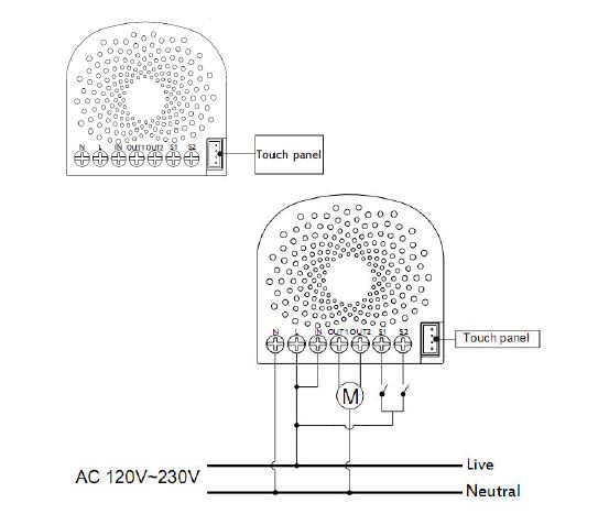
Notes for the wire connection ports:
Product Usage
Calibration of Nano Shutter (V 3.0 and later)
Calibration for Shutter has 2 modes: Shutter Mode and Venetian Mode.
In Shutter mode, only the Current Trip Time (Parameter 35) is used for up/down control.
In Venetian Mode, the Curtain Trip Time (Parameter 35) and Blade Turn Time (Parameter 34) are used for up/down control and angle of rotation of the leaf.
1. Shutter Mode
Used for standard roller blinds that move up and down only.
he calibration process is as follows:
a) Enter calibration mode
- By short pressing 3 times (Z-Wave button or external switch)
- Or by sending a CONFIGURATION SET Parameter 36 [1 byte] to value 1.
b) The curtain will begin to move to the end in one direction (full open or fully closed); reference point A.
- Press the Action Button/S1/S2 once the curtain is at max open or close to tell Nano Shutter to perform the next step.
c) The motor/curtain will reverse to other direction; reference point B.
- Press the Action Button/S1/S2 once the curent is at the max open or close to finalize the calibration.
d) Calibration is completed.
- Nano Shutter records the run time from the reference point A to B, which is the time between max open and the max close of the curtain (this time can be read and modified through the Configuration 0x23 (35) if additional readjustments are needed).
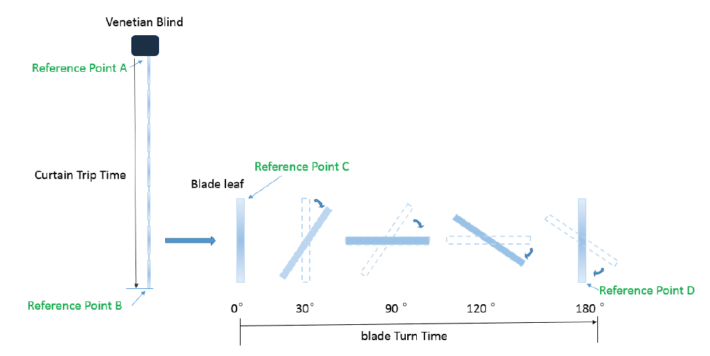
2. Venetian Mode
Nano Shutter in Venetian Mode can be set to open the blinds up/down, as well as the angle of rotation of the leaf
separately. There is a switch on Venetian to change the Controlling Channel for blind lifting and leaf rotation, the
switch needs manual operation by the user.
The calibration process is as follows:
a) Before calibration, set the Venetian to blind lifting channel; [Paramter 38 to value 1]
b) Enter Venetian calibration mode by:
- By short pressing 5 times (Z-Wave button or external switch)
- Or by sending a CONFIGURATION SET Parameter 36 [1 byte] to value 2.
c) The motor connected to Nano Shutter should move toward the direction in which the blinds are curled upwards (Reference C).
- Once the blinds are fully opened and curled upwards completely (Reference A and C):
- Press the Action Button/S1/S2 once to calibrate Reference A.
- If the blinds are unfolded, the motor movement direction needs to be reset by setting Parameter 22 to value 2; after setting the correct direction, follow step a to re-enter the calibration mode (step a);
d) Nano Shutter should now reverse the direction the motor blind movement downwards (Towards reference B). Once blinds close up completely (Reference point B):
- Press the Action Button/S1/S2 once to calibrate Reference B.
e) Nano Shutter will stop working and require that the Venetian blinds must be set to leaf rotation channel;
- Press the Action Button/S1/S2 once to start leaf rotation calibration.
f) The Venetian blinds should begin leaf rotation, the window leaf turn to 0° (reference point C).
- Press the Action Button/S1/S2 once the leaf is rotated completely.
g) The Venetian blinds will rotate to 180° (Reference point D).
- Press the Action Button/S1/S2 once the leaf is rotated completely to finalize calibration.
h) The Nano Shutter records the run time between points A and B, and turn time between reference points C and D which are curtain trip time and blade turn time (the recorded time can be read and modified from the Configuration 0x22 (34) and 0x23 (35)).
Operation Mode 1. - Split reaction between S1 and S2 controls.
| External Switch 1 (S1) | External Switch 2 (S2) | |||||
| Current State. | Stop | Moving to 100% | Moving to 0% | Stop | Moving to 0% | Moving to 100% |
| Button pressed once. | Move to 100% | Stop | NC | Move to 0% | Stop | NC |
Operation Mode 2. - Same controls over S1 and S2.
| External Switch 1 + 2 (S1 and S2 | |||||
| Current State | At 0% | Moving to 0% | Moving to 100% | At 100% | Stop |
| Button pressed once | Move to 100% | Stop | Stop | Move to 0% | Toggle |
The function of Action Button
Click one time
Quick press 2 times
Activate the automatic identification mode for external switch S1.
Note: When the Nano Shutter enters this mode, toggle the external switch S1 once and wait 2 seconds for the Nano Shutter to detect the external switch type of S1.
Quick press 3 times
Enter Shutter Calibration Mode
Orange light flashing when calibrating.
1. Press the Button/S1/S2 once when blinds arrive at max close.
2. Press the Button/S1/S2 again when blinds arrive at max open.
3. LED will stop when calibration is done.
Enter Venetian Calibration Mode
White light flashing when calibrating.
Quick press 6 times
Note:
Central Scene Notification (V3.0 and higher)
Switch 1
Key Pressed 1 time
Key Pressed 2 times
Key held Down (Push Button Supported Only)
Key Released (Push Button Supported Only)
Switch 2
Key Pressed 1 time
Key Pressed 2 times
Key held Down (Push Button Supported Only)
Key Released (Push Button Supported Only)
Note: Only Push Button mode switch support Attribut Key Held Down/Key Released
| Reset to factory default | Press the Action Button for 20 secounds |
| Inclusion | 1. Install the device according to the instructions. 2. Press the button on the Nano Shutter once. |
| Exclusion | 1. Press the button on the Nano Shutter 6 times. |
| NIF | Press the Action Button one time |
| Wakeup | XXXWakeupDescription |
| Protection | XXXProtection |
| FirmwareUpdate | XXXFirmwareUpdate |
| SetAssociation | XXXSetAssociation |
Association Groups:
| Group Number | Maximum Nodes | Description |
|---|---|---|
| 1 | 5 | Lifeline |
| 2 | 5 | Forward the Basic Set, Binary set, Scene Activation Set to associated nodes in Group 2 when the Nano Shutter receives the Basic Set, Binary set, Scene Activation Set commands. |
Configuration Parameters
Parameter 20: Motor behavior after Power ON (V3.0 and later)
Size: 1 Byte, Default Value: 0
| Setting | Description |
|---|---|
| 0 | Stay the same position before power off last time. |
| 1 | Moves to 99% |
| 2 | Moves to 0% |
Parameter 22: Determine motor run direction (V3.0 and later)
Change the mapping of output and motor running direction between the 2 directions below:na. Out1 maps forward and Out2 maps reversenb. Out1 maps reverse and Out2 maps forward Size: 1 Byte, Default Value: 2
| Setting | Description |
|---|---|
| 2 | Change direction |
Parameter 34: Blade Turn Time (V3.0 and later)
Note: For Venetian, if this value is set too large for blade turning, curtain may move upwards or downwards. Calibration need to work correctly.Or this setting will force the curtain to move up or down.nThis configuration will not change after network exclusion or Configuration Reset. Size: 2 Byte, Default Value: 150
| Setting | Description |
|---|---|
| 10 - 32767 | Configurable Range (0,1 - 327675 seconds) |
Parameter 35: Curtain Trip Time (V3.00 and later)
Note: For Venetian, if this value is set too large for curtain trip, blade turn positioning may cause errors. This configuration will not change after network exclusion or Configuration Reset. Size: 2 Byte, Default Value: 15000
| Setting | Description |
|---|---|
| 500 - 32767 | Configurable Range (5 - 327675 seconds) |
Parameter 35: Moving time (up to version 2.2)
Set the moving time from up (left) to down (right) for curtain. Size: 1 Byte, Default Value: 30
| Setting | Description |
|---|---|
| 1 - 255 | Moving time |
Parameter 36: Enter/Exit Calibration (V3.0 and later)
Note: Product will enter the right Curtain Mode after calibration, see Configuration 0x27 Size: 1 Byte, Default Value: 0
| Setting | Description |
|---|---|
| 0 | Set:Exit Calibration Report: Not in Calibration |
| 1 | Set:Enter Shutter Mode Calibration Report: In Shutter Mode Calibration |
| 2 | Set:Enter Venetian Mode Cal ibration Report: In Venetian Mode Calibration |
Parameter 37: User confirmation for calibration (V3.0 and later)
Size: 1 Byte, Default Value: 1
| Setting | Description |
|---|---|
| 1 | Go to next step of calibration |
Parameter 38: Return Calibration Status (Get or Report) (V3.0 and later)
Size: 1 Byte, Default Value: 0
| Setting | Description |
|---|---|
| 0 | Calibration Complete |
| 1 | Calibration starts, going to Reference Point A |
| 2 | Reach Reference Point A, going to Reference Point B |
| 3 | Reach Reference Point B, waiting for Blade turn Calibraion(Only for Venetian Mode) |
| 4 | Going to Reference Point C(Only for Venetian Mode) |
| 5 | Calibration terminated |
Parameter 39: Set the Curtain Mode (V3.0 and later)
Note: 1. This Operation will enter repositioning automatically;n2. This configuration will not change after network exclusion or Configuration Reset. Size: 1 Byte, Default Value: 0
| Setting | Description |
|---|---|
| 0 | Shutter Mode |
| 1 | Venetian Mode |
Parameter 40: Set repositioning begins (V3.0 and later)
Size: 1 Byte, Default Value: 1
| Setting | Description |
|---|---|
| 1 | Repositioning begins |
Parameter 41: Get repositioning Status (V3.0 and later)
Size: 1 Byte, Default Value: 0
| Setting | Description |
|---|---|
| 0 | Repositioning complete |
| 1 | In repositioning |
Parameter 42: Calibration Lock.Used to enable/disable calibration lock (V3.0 and later)
Size: 1 Byte, Default Value: 1
| Setting | Description |
|---|---|
| 0 | Disable calibration |
| 1 | Enable Action Button/ Command Calibration |
| 2 | Enable Action Button/ Command/S1/S2 Calibration |
Parameter 51: Curtain Trip Time for UP (Open) moving (V3.06 and later)
Size: 2 Byte, Default Value: 15000
| Setting | Description |
|---|---|
| 500 - 32767 | seconds |
Parameter 52: Curtain Trip Times for UP and Down are equal. (V3.06 and later)
Size: 1 Byte, Default Value: 1
| Setting | Description |
|---|---|
| 0 | The Curtain Trip Times for UP and Down are not equal |
| 1 | The Curtain Trip Times for UP and Down are equal |
Parameter 80: Report to group 1
To set which report would be sent to the associated nodes in association group 1 when the state of the output load is changed. Size: 1 Byte, Default Value: 0
| Setting | Description |
|---|---|
| 0 | Nothing |
| 1 | Basic Report CC |
| 2 | Switch Multilevel Report (V3.0 and later) |
Parameter 85: Operation mode of external switch
Set the operation mode of external switch. Operation Mode 1: Used S1 for close and S2 for opening the blind Operation Mode 2: Used both button for the same action Size: 1 Byte, Default Value: 0
| Setting | Description |
|---|---|
| 0 | Operation Mode 1 |
| 1 | Operation Mode 2 |
Parameter 120: Type of S1
Set the external switch mode of S1 Size: 1 Byte, Default Value: 0
| Setting | Description |
|---|---|
| 0 | Unidentified mode. |
| 2 | 3 way switch mode |
| 3 | Push button mode |
| 4 | Enter automatic identification mode (The blue Led will fast blink). |
Parameter 121: Type of S2
Set the external switch mode of S2 Size: 1 Byte, Default Value: 0
| Setting | Description |
|---|---|
| 0 | Unidentified mode |
| 2 | 3 way switch mode |
| 3 | push button mode |
| 4 | enter automatic identification mode (The green Led will fast blink). |
Parameter 248: Enable/Disable function of External Switch S1&S2 (V3.0 and later)
Note: This value can be combine, e.g. set to 3(1+2=3),means networking function and Reset function are both enable. Size: 1 Byte, Default Value: 1
| Setting | Description |
|---|---|
| 1 | Enable network function, inclusion/exclusion |
| 2 | Enable reset to factory default function |
Parameter 251: Enable/Disable function of External Touch Panel (V3.0 and later)
Enable/disable reset to factory default and exclusion function by long press on touch panel and press 6 times on wall swipe Size: 1 Byte, Default Value: 1
| Setting | Description |
|---|---|
| 0 | Disable |
Parameter 252: Enable/disable the configuration parameters to be locked. (up to version 2.2)
Size: 1 Byte, Default Value: 0
| Setting | Description |
|---|---|
| 0 | disabel |
| 1 | enable |
Parameter 255: Factory reset
Size: 4 Byte, Default Value:
| Setting | Description |
|---|---|
| 1431655765 | Factory Reset |
| 0 | Reset all configuration parameters to factory default settings |
Technical Data
| Dimensions | 0.0425000x0.0400000x0.0200000 mm |
| Weight | 34.24 gr |
| Hardware Platform | ZM5101 |
| EAN | 1220000016033 |
| IP Class | IP 20 |
| Voltage | 230V |
| Load | 10A |
| Device Type | Roller Shutter |
| Generic Device Class | Multilevel Switch |
| Specific Device Class | Motor Control Device (A) |
| Firmware Version | 03 |
| Z-Wave Version | 6.81 |
| Certification ID | ZC10-18066132 |
| Z-Wave Product Id | 0x0371.0x0003.0x008d |
| Frequency | Europe - 868,4 Mhz |
| Maximum transmission power | 5 mW |