Aeotec
TriSensor
SKU: AEOEZWA005


Quickstart
This is a
Important safety information
Please read this manual carefully. Failure to follow the recommendations in this manual may be dangerous or may violate the law. The manufacturer, importer, distributor and seller shall not be liable for any loss or damage resulting from failure to comply with the instructions in this manual or any other material. Use this equipment only for its intended purpose. Follow the disposal instructions. Do not dispose of electronic equipment or batteries in a fire or near open heat sources.What is Z-Wave?
Z-Wave is the international wireless protocol for communication in the Smart Home. This device is suited for use in the region mentioned in the Quickstart section.
Z-Wave ensures a reliable communication by reconfirming every message (two-way communication) and every mains powered node can act as a repeater for other nodes (meshed network) in case the receiver is not in direct wireless range of the transmitter.
This device and every other certified Z-Wave device can be used together with any other certified Z-Wave device regardless of brand and origin as long as both are suited for the same frequency range.
If a device supports secure communication it will communicate with other devices secure as long as this device provides the same or a higher level of security. Otherwise it will automatically turn into a lower level of security to maintain backward compatibility.
For more information about Z-Wave technology, devices, white papers etc. please refer to www.z-wave.info.
Product Description
TriSensor can be included and operated in any Z-Wave network with other Z-Wave certified devices from other manufacturers and/or other applications. All non-battery operated nodes within the network will act as repeaters regardless of vendor to increase reliability of the network. If PIR motion sensor is triggered, the TriSensor will send a Basic set to associated devices.The PIR motion sensor will then become inactive. If no PIR motion is triggered after the PIR interval time (configurable), the TriSensor will send Basic Set to the associated nodes.
Prepare for Installation / Reset
Please read the user manual before installing the product.
In order to include (add) a Z-Wave device to a network it must be in factory default state. Please make sure to reset the device into factory default. You can do this by performing an Exclusion operation as described below in the manual. Every Z-Wave controller is able to perform this operation however it is recommended to use the primary controller of the previous network to make sure the very device is excluded properly from this network.
Reset to factory default
This device also allows to be reset without any involvement of a Z-Wave controller. This procedure should only be used when the primary controller is inoperable.
1. Power up the device.
2. Press and hold the button for 15s until Red Led is blinking,then release the button
Safety Warning for Batteries
The product contains batteries. Please remove the batteries when the device is not used. Do not mix batteries of different charging level or different brands.
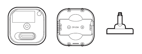
Installation
With your TriSensor now a part of your Z-Wave network and having determined its installation location, its time to finish its physical installation. There are 2 ways that your TriSensor can be mounted on a wall or ceiling. Most simply it can be placed upon a shelf without the need to attach further accessories. You can mount your sensor in a corner or against a wall or ceiling by using the Back-Mount Plate. Its also possible to embed your TriSensor within a ceiling or wall using its Recessor accessory (sold separately).
To install your TriSensor:
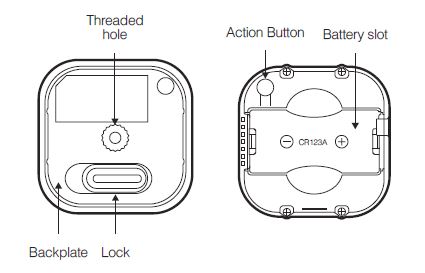
Reattach the three parts of your TriSensor to each other. Unlock the Battery Cover from the Sensor unit.
You may also install your TriSensor on any flat surface area such as tables, and bookshelves;

You can place it upon a shelf without the need to attach further accessories.
To install your TriSensor with the Back-Mount Plate;
1. You can affix the Back-Mount Arm by Double-Sided Tape or using the provided KA2.5-20 mm screws.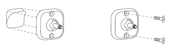
Tips: We suggest you choose the second method (using screws to affix the Back-Mount Arm) which would be more stable.
2. After you have completed the affixing of Back-Mount Arm, you will need to lock TriSensor to the Back-Mount Arm by screwing TriSensor in.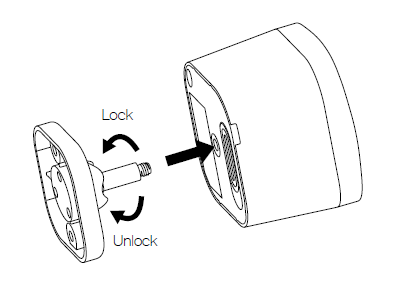
3. The Back-Mount Arm may be locked at various angles by turning the Friction Lock clockwise and counter-clockwise to respectively tighten or loosen the angle of the arm. You can rotate the Friction Lock to change the measurement area of sensor.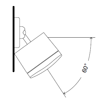
Inclusion/Exclusion
On factory default the device does not belong to any Z-Wave network. The device needs to be added to an existing wireless network to communicate with the devices of this network. This process is called Inclusion.
Devices can also be removed from a network. This process is called Exclusion. Both processes are initiated by the primary controller of the Z-Wave network. This controller is turned into exclusion respective inclusion mode. Inclusion and Exclusion is then performed doing a special manual action right on the device.
Inclusion
1. Open the battery compartment.2. Press the button once.
Exclusion
1. Open the battery compartment.2. Press the button once.
Product Usage
Choosing a Location for your TriSensor.
TriSensor can bring its intelligent readings to many locations of your home. Before deciding on a location, there are some things you should first consider.
TriSensors motion sensor uses light and heat readings to determine motion; sudden light and heating changes can impact the sensors quality of motion readings. As such, your sensor should not be installed in areas of artificial temperature change. Thus, when selecting a location, avoid placing it beside or near air conditioners, and heaters.
Your TriSensor will be powered by batteries, you should avoid installing it in a location where the temperature can drop below 0°C / 32°F - this is below the any battery operational use point. Selecting a location for your sensor also depends on the layout of any area that you want monitored. Whatever the room or area, please ensure that it fits with your sensors effective motion sensing range as described in the following diagrams.
For optimal performance, your TriSensor should NOT be mounted directly on or near metal framing or other large metallic objects. Large metal objects may weaken the Z-Wave wireless signal TriSensor depends on for communication due to the wireless reflective properties of metal.
TriSensor maximum motion detection range is: 23ft or 7m.
Outdoor installation.
Please note that when installed outdoors of your home, your TriSensor should only be relied on for temperature and light where as the motion sensing capabilities should be disabled on your gateway in order to avoid false motion readings. If selecting an outdoor location, its important to position your TriSensor in a sheltered location. It is best if your TriSensor is not directly exposed to rain, snow, or other elements.
If you wish to use TriSensor outdoors, you will need to lower settings, and angle TriSensor accordingly as all environments will require different solutions or different settings for the motion sensor to work properly. Parameter 3 [1 byte] will determine the sensitivity of the motion sensor from a value range of 0 disabled to 11 max sensitivity (your ability to configure this setting will depend on the gateway used).
It is advised that if you are seeing false motion tracking, run trial and error to determine the best sensitivity from a range of 0 - 11 by going down 1 sensitivity level after every test (first 5, 4, 3, 2, then 1), while setting Parameter 3 [2 byte] to 5 to allow a PIR sensor timeout of 5 seconds after detecting motion to rapidly determine the best settings for motion use outdoors.
Communication to a Sleeping device (Wakeup)
This device is battery operated and turned into deep sleep state most of the time to save battery life time. Communication with the device is limited. In order to communicate with the device, a static controller C is needed in the network. This controller will maintain a mailbox for the battery operated devices and store commands that can not be received during deep sleep state. Without such a controller, communication may become impossible and/or the battery life time is significantly decreased.
This device will wakeup regularly and announce the wakeup state by sending out a so called Wakeup Notification. The controller can then empty the mailbox. Therefore, the device needs to be configured with the desired wakeup interval and the node ID of the controller. If the device was included by a static controller this controller will usually perform all necessary configurations. The wakeup interval is a tradeoff between maximal battery life time and the desired responses of the device. To wakeup the device please perform the following action: Press and hold the button at least 2s until Red Led is on and then release the button,device will send wakeup notification to controller if device is in a Z-Wave network.
Quick trouble shooting
Here are a few hints for network installation if things dont work as expected.
- Make sure a device is in factory reset state before including. In doubt exclude before include.
- If inclusion still fails, check if both devices use the same frequency.
- Remove all dead devices from associations. Otherwise you will see severe delays.
- Never use sleeping battery devices without a central controller.
- Dont poll FLIRS devices.
- Make sure to have enough mains powered device to benefit from the meshing
Association - one device controls an other device
Z-Wave devices control other Z-Wave devices. The relationship between one device controlling another device is called association. In order to control a different device, the controlling device needs to maintain a list of devices that will receive controlling commands. These lists are called association groups and they are always related to certain events (e.g. button pressed, sensor triggers, ...). In case the event happens all devices stored in the respective association group will receive the same wireless command wireless command, typically a 'Basic Set' Command.
Association Groups:
| Group Number | Maximum Nodes | Description |
|---|---|---|
| 1 | 5 | Lifeline |
| 2 | 5 | Controlling group, all nodes associated in this group will be controlled through BASIC_SET command by the device when device detects a movement event. Basic Set Value is decided by Configuration Parameter 6. |
| 3 | 5 | Controlling group, all nodes associated in this group will be controlled through BASIC_SET command by the device when device detects an ambient temperature alarm (Decided by Configuration Parameter 7). |
Configuration Parameters
Z-Wave products are supposed to work out of the box after inclusion, however certain configuration can adapt the function better to user needs or unlock further enhanced features.
IMPORTANT: Controllers may only allow configuring signed values. In order to set values in the range 128 ... 255 the value sent in the application shall be the desired value minus 256. For example: To set a parameter to 200 it may be needed to set a value of 200 minus 256 = minus 56. In case of a two byte value the same logic applies: Values greater than 32768 may needed to be given as negative values too.
Parameter 1: Motion Retrigger Time
This parameter is configured the delay time before PIR sensor can be triggered again to reset motion timeout counter. Size: 2 Byte, Default Value: 30
| Setting | Description |
|---|---|
| 0 | Will disable PIR sensor from triggering until motion timeout has finished. |
| 1 - 32767 | Time in seconds |
Parameter 2: Motion Clear Time
This parameter is configured the time to clear motion event after a motion event detected. Time to motion clear, the device will send a clear event report to controller and send BASIC_SET= 0x00 to nodes associated in group 2. Size: 2 Byte, Default Value: 240
| Setting | Description |
|---|---|
| 1 - 32767 | Second |
Parameter 3: Motion Sensitivity
This parameter is configured the sensitivity that motion detect. 0PIR sensor disabled. Size: 1 Byte, Default Value: 11
| Setting | Description |
|---|---|
| 0 | Disable |
| 1 - 11 | Sensitivity. |
Parameter 4: Binary Sensor Report Enable
Size: 1 Byte, Default Value: 0
| Setting | Description |
|---|---|
| 0 | Disable sensor binary report when motion event is detected or cleared. |
| 1 | Enable sensor binary report when motion event is detected or cleared. |
Parameter 5: Disable BASIC_SET to Associatednodes
This parameter is configured the enabled or disabled send BASIC_SET command to nodes that associated in group 2 and group 3. Size: 1 Byte, Default Value: 3
| Setting | Description |
|---|---|
| 0 | Disabled All Group Basic Set Command |
| 1 | Enabled Group 2 Basic Set Command, Group 3 Basic Set Command is disabled. |
| 2 | Enabled Group 3 Basic Set Command, Group 2 Basic Set Command is disabled. |
| 3 | Enabled Group 2 and Group 3 Basic Set Command. |
Parameter 6: Basic Set Value Settings for Group 2
Size: 1 Byte, Default Value: 0
| Setting | Description |
|---|---|
| 0 | Send BASIC_SET = 0xFF to devices associated in Group 2 when motion event is triggered, send BASIC_SET = 0x00 to devices associated in group 2 when motion event is cleared. |
| 1 | Send BASIC_SET = 0x00 to devices associated in Group 2 when motion event is triggered, send BASIC_SET = 0xFF to devices associated in group 2 when motion event is cleared. |
| 2 | Send BASIC_SET = 0xFF to devices associated in Group 2 when motion event is triggered. |
| 3 | Send BASIC_SET = 0x00 to devices associated in Group 2 when motion event is triggered. |
| 4 | Send BASIC_SET = 0x00 to devices associated in Group 2 when motion event is cleared. |
| 5 | Send BASIC_SET = 0xFF to devices associated in Group 2 when motion event is cleared. |
Parameter 7: Temperature Alarm Value
This parameter is configured the threshold value that alarm level for temperature. When the current ambient temperature value is larger than this configuration value, device will send a BASIC_SET = 0xFF to nodes associated in group 3. If current temperature value is less than this value, device will send a BASIC_SET = 0x00 to nodes associated in group 3.Value = [Value]0.1(Celsius / Fahrenheit) Size: 2 Byte, Default Value: 239
| Setting | Description |
|---|---|
| -400 - 850 | Value = 0.1(Celsius / Fahrenheit) |
Parameter 10: Led Indicate Disable
This parameter is configured the Led light on disable or enable. This configuration is not affect inclusion, exclusion and reset. Size: 1 Byte, Default Value: 1
| Setting | Description |
|---|---|
| 0 | Disable Led Blink. |
| 1 | Enable Led Blink when device detects a motion event. |
Parameter 11: Led Color For Motion EventReport
Size: 1 Byte, Default Value: 2
| Setting | Description |
|---|---|
| 0 | Disable |
| 1 | Red |
| 2 | Green |
| 3 | Blue |
| 4 | Yellow |
| 5 | Pink |
| 6 | Cyan |
| 7 | Purple |
| 8 | Orange |
Parameter 12: Led Color For Temperature SensorReport
Size: 1 Byte, Default Value: 0
| Setting | Description |
|---|---|
| 0 | Disable |
| 1 | Red |
| 2 | Green |
| 3 | Blue |
| 4 | Yellow |
| 5 | Pink |
| 6 | Cyan |
| 7 | Purple |
| 8 | Orange |
Parameter 13: Led Color For Light Sensor Report
Size: 1 Byte, Default Value: 0
| Setting | Description |
|---|---|
| 0 | Disable |
| 1 | Red |
| 2 | Green |
| 3 | Blue |
| 4 | Yellow |
| 5 | Pink |
| 6 | Cyan |
| 7 | Purple |
| 8 | Orange |
Parameter 14: Led Color For Battery Report
Size: 1 Byte, Default Value: 0
| Setting | Description |
|---|---|
| 0 | Disable |
| 1 | Red |
| 2 | Green |
| 3 | Blue |
| 4 | Yellow |
| 5 | Pink |
| 6 | Cyan |
| 7 | Purple |
| 8 | Orange |
Parameter 15: Led Color For Wakeup NotificationReport
Size: 1 Byte, Default Value: 0
| Setting | Description |
|---|---|
| 0 | Disable |
| 1 | Red |
| 2 | Green |
| 3 | Blue |
| 4 | Yellow |
| 5 | Pink |
| 6 | Cyan |
| 7 | Purple |
| 8 | Orange |
Parameter 20: Temperature Scale Setting
Configure temperature sensor scale type, Temperature to report in Celsius or Fahrenheit. Size: 1 Byte, Default Value: 0
| Setting | Description |
|---|---|
| 0 | Celsius (C) |
| 1 | Fahrenheit (F) |
Parameter 21: Temperature Threshold Value toReport
Change threshold value for change in temperature to induce an automatic report for temperature sensor. Scale is identical setting in Parameter No.20. Setting of value 20 can be a change of -2.0 or +2.0 (C or F depending on Parameter No.20) to induce automatic report or setting a value of 2 will be a change of 0.2(C or F). Size: 2 Byte, Default Value: 20
| Setting | Description |
|---|---|
| 0 - 250 | Value in 0,1° |
Parameter 22: Light intensity Threshold Value to Report
Change threshold value for change in light sensor to induce an automatic report for temperature sensor. Size: 2 Byte, Default Value: 100
| Setting | Description |
|---|---|
| 0 - 10000 | Lux. |
Parameter 23: Temperature Sensor ReportInterval
This parameter is configured the time interval for temperature sensor report. This value is larger, the battery life is longer. And the temperature value changed is not obvious. Size: 2 Byte, Default Value: 3600
| Setting | Description |
|---|---|
| 1 - 32767 | Second. |
Parameter 24: Light Sensor Report Interval
This parameter is configured the time interval for light sensor report. This value is larger, the battery life is longer. And the light intensity changed is not obvious. Size: 2 Byte, Default Value: 3600
| Setting | Description |
|---|---|
| 1 - 32767 | Second. |
Parameter 30: Temperature Offset Value
The current measuring temperature value can be add and minus a value by this setting. The scale can be decided by Parameter Number 20.Temperature Offset Value = [Value] * 0.1(Celsius / Fahrenheit) Size: 2 Byte, Default Value: 0
| Setting | Description |
|---|---|
| -200 - 200 | Temperature Offset Value = [Value] * 0.1(Celsius / Fahrenheit) |
Parameter 31: Light Intensity Offset Value
The current measuring light intensity value can be add and minus a value by this setting. Size: 2 Byte, Default Value: 0
| Setting | Description |
|---|---|
| -1000 - 1000 | Lux. |
Parameter 100: Light Sensor Calibrated Coefficient
This configuration defines the calibrated scale for ambient light intensity. Because the method and position that the sensor mounted and the cover of sensor will bring measurement error, user can get more real light intensity by this parameter setting. User should run the steps as blows for calibrating1)Set this parameter value to default (Assumes the sensor has been added in a Z-Wave Network).2)Place a digital luxmeter close to sensor and keep the same direction, monitor the light intensity value (Vm) which report to controller and record it. The same time user should record the value (Vs) of luxmeter.3)The scale calibration formula: k = Vm / Vs.4)The value of k is then multiplied by 1024 and rounded to the nearest whole number.5)Set the value getting in to this parameter, calibrate finished.For example, Vm = 300, Vs = 2600, then k = 2600 / 300 = 8.6667k = 8.6667 * 1024 = 8874.78875The parameter should be set to 8875. Size: 2 Byte, Default Value: 1024
| Setting | Description |
|---|---|
| 1 - 32767 | This configuration defines the calibrated scale for ambient light intensity. Because the method and position that the sensor mounted and the cover of sensor will bring measurement error, user can get more real light intensity by this parameter setting. |
Technical Data
| Dimensions | 45 x 45 x 60 mm |
| Weight | 35 gr |
| Hardware Platform | ZM5101 |
| EAN | 1220000016132 |
| IP Class | IP 20 |
| Voltage | 3V |
| Battery Type | 1 * CR123A |
| Device Type | Notification Sensor |
| Network Operation | Reporting Sleeping Slave |
| Z-Wave Version | 6.71.01 |
| Certification ID | ZC10-18046087 |
| Z-Wave Product Id | 0x0371.0x0002.0x0005 |
| Supported Notification Types | Home Security |
| Sensors | Air TemperatureLuminanceMotion/No Motion (Binary) |
| Color | White |
| Frequency | Europe - 868,4 Mhz |
| Maximum transmission power | 5 mW |
Supported Command Classes
- Association Grp Info
- Association V2
- Battery
- Configuration
- Device Reset Locally
- Firmware Update Md V4
- Manufacturer Specific V2
- Multi Channel Association V3
- Notification V8
- Powerlevel
- Security 2
- Security
- Sensor Binary V2
- Sensor Multilevel V7
- Supervision
- Transport Service V2
- Version V2
- Wake Up V2
- Zwaveplus Info V2
Controlled Command Classes
- Basic
Explanation of Z-Wave specific terms
- Controller — is a Z-Wave device with capabilities to manage the network. Controllers are typically Gateways,Remote Controls or battery operated wall controllers.
- Slave — is a Z-Wave device without capabilities to manage the network. Slaves can be sensors, actuators and even remote controls.
- Primary Controller — is the central organizer of the network. It must be a controller. There can be only one primary controller in a Z-Wave network.
- Inclusion — is the process of adding new Z-Wave devices into a network.
- Exclusion — is the process of removing Z-Wave devices from the network.
- Association — is a control relationship between a controlling device and a controlled device.
- Wakeup Notification — is a special wireless message issued by a Z-Wave device to announces that is able to communicate.
- Node Information Frame — is a special wireless message issued by a Z-Wave device to announce its capabilities and functions.