Aeotec
Smart Boost Timer Switch
SKU: AEOEZWA006


Quickstart
This is a
2. Put the Z-Wave Primary Controller into inclusion mode (If you dont know how to do this, refer to its manual)
3. Press and hold the action button, and when the yellow LED is on, release the button. It indicates the device has enter learn mode.
4. If added successfully, the power LED will remain green for 2 seconds, then turn off.
Important safety information
Please read this manual carefully. Failure to follow the recommendations in this manual may be dangerous or may violate the law. The manufacturer, importer, distributor and seller shall not be liable for any loss or damage resulting from failure to comply with the instructions in this manual or any other material. Use this equipment only for its intended purpose. Follow the disposal instructions. Do not dispose of electronic equipment or batteries in a fire or near open heat sources.What is Z-Wave?
Z-Wave is the international wireless protocol for communication in the Smart Home. This device is suited for use in the region mentioned in the Quickstart section.
Z-Wave ensures a reliable communication by reconfirming every message (two-way communication) and every mains powered node can act as a repeater for other nodes (meshed network) in case the receiver is not in direct wireless range of the transmitter.
This device and every other certified Z-Wave device can be used together with any other certified Z-Wave device regardless of brand and origin as long as both are suited for the same frequency range.
If a device supports secure communication it will communicate with other devices secure as long as this device provides the same or a higher level of security. Otherwise it will automatically turn into a lower level of security to maintain backward compatibility.
For more information about Z-Wave technology, devices, white papers etc. please refer to www.z-wave.info.
Product Description
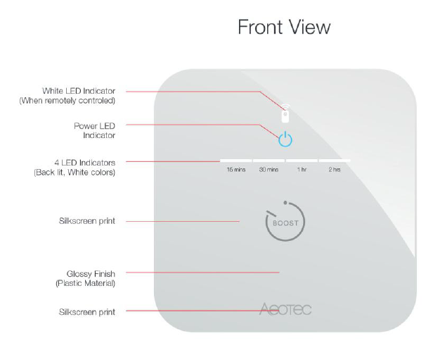
The Aeotec Smart Boost Timer Switch is a Z-Wave Plus enabled device and can be included/operated in any Z-Wave network with other Z-Wave certified devices from other manufacturers and/or other applications. All non-battery operated nodes within the network will act as repeaters regardless of vendor to increase reliability of the network.The Aeotec Smart Boost Time Switch supports consumption meter function. When the device has been included in the network, it will report the consumption power periodically. It is also a high output countdown timer that can be used to control immersion heater elements or other electrical appliances rated up to 16A. On the product, four simple white LEDs are used to show the user how much time is left to run. Pressing the switch whilst the unit is operating allows the user to cancel the timing program,and the memory function of the timer will remember the last period selected.
Prepare for Installation / Reset
Please read the user manual before installing the product.
In order to include (add) a Z-Wave device to a network it must be in factory default state. Please make sure to reset the device into factory default. You can do this by performing an Exclusion operation as described below in the manual. Every Z-Wave controller is able to perform this operation however it is recommended to use the primary controller of the previous network to make sure the very device is excluded properly from this network.
Reset to factory default
This device also allows to be reset without any involvement of a Z-Wave controller. This procedure should only be used when the primary controller is inoperable.
- Press and hold the Action Button for 15 seconds, at 15 seconds the LED indicator will turn red.
- Release the button on Smart Boost Timer Switch.
- If the factory reset is successful, the LED Indicator will start to blink blue slowly.
Safety Warning for Mains Powered Devices
ATTENTION: only authorized technicians under consideration of the country-specific installation guidelines/norms may do works with mains power. Prior to the assembly of the product, the voltage network has to be switched off and ensured against re-switching.
Installation
Wiring your Smart Boost Timer Switch.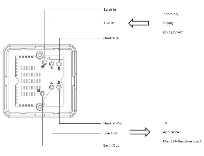
Wiring incoming power supply to Switch (To Incoming Supply / Input Power side):
- Ensure that no power is present in the AC Live (80 - 250VAC) and Neutral wire and test them with a Voltage Screwdriver or Multimeter to make sure.
- Connect AC Live (80 - 250VAC) wire to L terminal over Incoming power.
- Connect AC Neutral wire to N terminal over incoming power.
- Connect Ground wire to Earth terminal over incoming power.
- Make sure to screw in all terminals tight so that the wires do not slip out during use.
Wiring your Load to Switch (To Appliance / Load side):
- Connect Live input wire from your Load to L terminal on the load side.
- Connect Neutral input wire from your Load to N terminal on the load side.
- Connect Ground input wire from your Load to Earth terminal on the load side.
- Make sure to screw in all terminals tight so that the wires do not slip out during use.
Inclusion/Exclusion
On factory default the device does not belong to any Z-Wave network. The device needs to be added to an existing wireless network to communicate with the devices of this network. This process is called Inclusion.
Devices can also be removed from a network. This process is called Exclusion. Both processes are initiated by the primary controller of the Z-Wave network. This controller is turned into exclusion respective inclusion mode. Inclusion and Exclusion is then performed doing a special manual action right on the device.
Inclusion
Exclusion
1. Press the Smart Boost Timer switch 3 times quickly.Product Usage
Understanding the Power Indicator color signals.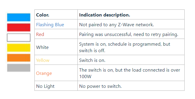
Smart Boost Timer Switch Modes.
There are 2 separate modes for Smart Boost Timer Switch: Boost Mode or Override Schedule Mode.
Boost mode.
Boost mode will allow you to turn on your Smart Boost Timer Switch to 4 pre-programmed set times (configurable via Parameter 5) before turning off Smart Boost Timer Switch. Each time you press and hold your Smart Boost Timer Switch button for 1 second and release, this will increase the amount of time by 30 minutes up to 120 minutes maximum before turning off the switch.
Parameter 5 boost time setting.
Configures the boost time interval in minutes.

Controlling boost mode.
Boost mode has 4 settings which is configurable by Parameter 5 to allow you to configure the time settings of each boost mode.
![]()
Each time you press and hold the Action Button for 1 second then release, you will increase boost mode up to 4 separate settings in increments of 30 minutes.
- Press and hold for 1 second then release.
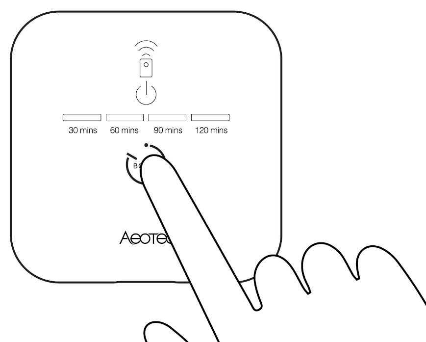
Boost mode 1 (LED 1 on) - Keeps your Smart Boost Timer Switch ON for 30 minutes (or configuration setting set on Parameter 5)
Boost mode 2 (LED 1 and 2 on) - Keeps your Smart Boost Timer Switch ON for 60 minutes (or configuration setting set on Parameter 5)
Boost mode 3 (LED 1, 2, and 3 on) - Keeps your Smart Boost Timer Switch ON for 90 minutes (or configuration setting set on Parameter 5)
Boost mode 4 (LED 1, 2, 3, and 4 on) - Keeps your Smart Boost Timer Switch ON for 120 minutes (or configuration setting set on Parameter 5)
Override schedule mode.
Override Mode will override all schedules and time programmed to Smart Boost Timer Switch to allow you to manually control it through your gateway just like any other smart switch.
Changing between boost and override modes.
The mode of Smart Boost Timer Switch can be changed by pressing and holding the Action Button of Smart Boost Timer Switch for 5 seconds.
- Press and hold Action Button for 5 seconds.
- At 5 seconds, the Power Indicator light will turn green, release the button to complete the mode change.
- If the LED turns red after release, this indicates that Smart Boost Power Switch has changed to Boost mode.
Quick trouble shooting
Here are a few hints for network installation if things dont work as expected.
- Make sure a device is in factory reset state before including. In doubt exclude before include.
- If inclusion still fails, check if both devices use the same frequency.
- Remove all dead devices from associations. Otherwise you will see severe delays.
- Never use sleeping battery devices without a central controller.
- Dont poll FLIRS devices.
- Make sure to have enough mains powered device to benefit from the meshing
Association - one device controls an other device
Z-Wave devices control other Z-Wave devices. The relationship between one device controlling another device is called association. In order to control a different device, the controlling device needs to maintain a list of devices that will receive controlling commands. These lists are called association groups and they are always related to certain events (e.g. button pressed, sensor triggers, ...). In case the event happens all devices stored in the respective association group will receive the same wireless command wireless command, typically a 'Basic Set' Command.
Association Groups:
| Group Number | Maximum Nodes | Description |
|---|---|---|
| 1 | 5 | Lifeline |
| 2 | 5 | Send Basic Set to Nodes |
Configuration Parameters
Z-Wave products are supposed to work out of the box after inclusion, however certain configuration can adapt the function better to user needs or unlock further enhanced features.
IMPORTANT: Controllers may only allow configuring signed values. In order to set values in the range 128 ... 255 the value sent in the application shall be the desired value minus 256. For example: To set a parameter to 200 it may be needed to set a value of 200 minus 256 = minus 56. In case of a two byte value the same logic applies: Values greater than 32768 may needed to be given as negative values too.
Parameter 1: Power out action
Action in case of power out. This parameter is used to configure the device state after power on. Size: 1 Byte, Default Value: 3
| Setting | Description |
|---|---|
| 0 | keep the last state when re-power on |
| 1 | power on |
| 2 | power off |
| 3 | return to standard schedule (see schedule command class) so this would either be on or off depending on schedule and the time. |
Parameter 2: LED status
Configure LED (except boost) to be off irrespective of switch status. Size: 1 Byte, Default Value: 1
| Setting | Description |
|---|---|
| 0 | Disable all LED except for boost |
| 1 | Enable all LED indication |
| 2 | Momentary mode (LED turns on for 5 seconds, then turn off LED) |
Parameter 3: Auto off timer
Timer acts as auto off after specified minutes, setting is set in seconds. Size: 4 Byte, Default Value: 0
| Setting | Description |
|---|---|
| 0 | No auto off with timer |
| 1 - 86400 | Auto off after this specified time, unit second. |
Parameter 4: Current overload protection
Current and overload protection Size: 1 Byte, Default Value: 1
| Setting | Description |
|---|---|
| 0 | Disable current and overload protection |
| 1 | Enable current and overload protection |
Parameter 5: Boost time
Configure boost time interval, unit minute. Size: 2 Byte, Default Value: 30
| Setting | Description |
|---|---|
| 1 - 255 | When user press the boost button one time, the boost time will increase 30 (the value can be changed) minutes. |
Parameter 7: LED threshold setting
This parameter is used to configure the power led threshold, unit W. When the load <= 100W, the power led will indicate yellow. When the load > 100W, the power led will indicate orange. When no load, the power led will indicate white. Size: 2 Byte, Default Value: 100
| Setting | Description |
|---|---|
| 0 - 3000 | Enabled threshold |
Parameter 20: kWh threshold setting
Threshold settings for energy kWh. When the energy above the threshold, it will send a meter report command to gateway. Size: 2 Byte, Default Value: 100
| Setting | Description |
|---|---|
| 0 | Disable report |
| 1 - 10000 | Enable report |
Parameter 21: Watt threshold setting
Threshold settings for Watt automatic report, unit W. When Watt above the threshold, it will send a meter report command to gateway. Size: 2 Byte, Default Value: 100
| Setting | Description |
|---|---|
| 0 | Disable |
| 1 - 2500 | Enable |
Parameter 22: Current threshold setting
Threshold settings for Current automatic report, unit 0.1A. When current above the threshold, it will send a meter report command to gateway. Size: 2 Byte, Default Value: 0
| Setting | Description |
|---|---|
| 0 | Disable |
| 1 - 130 | Enable |
Parameter 23: Watt report interval
Watt automatic report interval, unit second. Size: 4 Byte, Default Value: 600
| Setting | Description |
|---|---|
| 0 | disable |
| 30 - 65535 | enable |
Parameter 24: kWh report interval
kWh automatic report interval, unit second. Size: 4 Byte, Default Value: 600
| Setting | Description |
|---|---|
| 0 | disable |
| 30 - 65535 | enable |
Parameter 25: Voltage report interval
Voltage automatic report interval, unit second. Size: 4 Byte, Default Value: 600
| Setting | Description |
|---|---|
| 0 | disable |
| 30 - 65535 | enable |
Parameter 26: Current report interval
Current automatic report interval, unit second. Size: 4 Byte, Default Value: 600
| Setting | Description |
|---|---|
| 0 | disable |
| 30 - 65535 | enable |
Technical Data
| Dimensions | 100 x 55 x 25 mm |
| Weight | 165 gr |
| Hardware Platform | ZM5101 |
| EAN | 1220000016194 |
| IP Class | IP 20 |
| Battery Type | 1 * CR2032 |
| Device Type | On/Off Power Switch |
| Network Operation | Always On Slave |
| Z-Wave Version | 6.81.01 |
| Certification ID | ZC10-18106255 |
| Z-Wave Product Id | 0x0371.0x0003.0x00B4 |
| Supported Meter Type | Electric Energy |
| Firmware Updatable | Updatable by Consumer by RF |
| Color | White |
| Sensors | Power |
| Electric Load Type | Incandescent |
| Neutral Wire Required | ok |
| Switch Type | Push Button |
| Frequency | Europe - 868,4 Mhz |
| Maximum transmission power | 5 mW |
Supported Command Classes
- Association Grp Info
- Association V2
- Basic V2
- Clock
- Configuration
- Device Reset Locally
- Firmware Update Md V4
- Manufacturer Specific V2
- Meter V5
- Multi Channel Association V3
- Powerlevel
- Schedule
- Security
- Security 2
- Sensor Multilevel V11
- Supervision
- Switch Binary
- Transport Service V2
- Version V3
- Zwaveplus Info V2
Controlled Command Classes
- Basic V2
Explanation of Z-Wave specific terms
- Controller — is a Z-Wave device with capabilities to manage the network. Controllers are typically Gateways,Remote Controls or battery operated wall controllers.
- Slave — is a Z-Wave device without capabilities to manage the network. Slaves can be sensors, actuators and even remote controls.
- Primary Controller — is the central organizer of the network. It must be a controller. There can be only one primary controller in a Z-Wave network.
- Inclusion — is the process of adding new Z-Wave devices into a network.
- Exclusion — is the process of removing Z-Wave devices from the network.
- Association — is a control relationship between a controlling device and a controlled device.
- Wakeup Notification — is a special wireless message issued by a Z-Wave device to announces that is able to communicate.
- Node Information Frame — is a special wireless message issued by a Z-Wave device to announce its capabilities and functions.