Aeon Labs
Z-Wave Clamp Power Meter 1st Edition - two clamps
SKU: AEO_HEM2-G1
Quickstart
This is a
Single click the little button behind the battery cover to include or exclude the device. The device is FLIRS.
Important safety information
Please read this manual carefully. Failure to follow the recommendations in this manual may be dangerous or may violate the law. The manufacturer, importer, distributor and seller shall not be liable for any loss or damage resulting from failure to comply with the instructions in this manual or any other material. Use this equipment only for its intended purpose. Follow the disposal instructions. Do not dispose of electronic equipment or batteries in a fire or near open heat sources.What is Z-Wave?
Z-Wave is the international wireless protocol for communication in the Smart Home. This device is suited for use in the region mentioned in the Quickstart section.
Z-Wave ensures a reliable communication by reconfirming every message (two-way communication) and every mains powered node can act as a repeater for other nodes (meshed network) in case the receiver is not in direct wireless range of the transmitter.
This device and every other certified Z-Wave device can be used together with any other certified Z-Wave device regardless of brand and origin as long as both are suited for the same frequency range.
If a device supports secure communication it will communicate with other devices secure as long as this device provides the same or a higher level of security. Otherwise it will automatically turn into a lower level of security to maintain backward compatibility.
For more information about Z-Wave technology, devices, white papers etc. please refer to www.z-wave.info.
Product Description
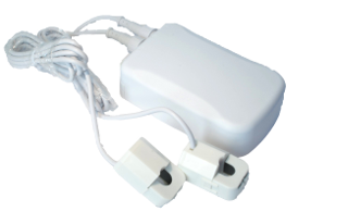
The Aeon Labs Smart Energy Monitor is a low-cost energy monitor for the entire home. It can wirelessly report immediate wattage and kWh usage to central control point gateways and can be easily and safely installed by anyone. Ease and safety are paramount: Electricians are not required to install the Aeon Labs Smart Energy Monitor; the customer never needs to handle hot exposed wiring. Current transformer clamps clamp around the AC Mains to detect energy usage for the entire house. The main body is anchored using a back mount which can be opend easily for battery replacement (every year). Optionally it is possible to power the unit from an external mini USB power supply. The device reports W and kWH.
Prepare for Installation / Reset
Please read the user manual before installing the product.
In order to include (add) a Z-Wave device to a network it must be in factory default state. Please make sure to reset the device into factory default. You can do this by performing an Exclusion operation as described below in the manual. Every Z-Wave controller is able to perform this operation however it is recommended to use the primary controller of the previous network to make sure the very device is excluded properly from this network.
Safety Warning for Batteries
The product contains batteries. Please remove the batteries when the device is not used. Do not mix batteries of different charging level or different brands.
Installation

The HEM can be placed on every dry place closed to the electric installation to be monitored. The current transformers need to be clamped around single wires. Attention: It is not possible to measure the current in cables that consist of more than one wire. Such a wire must be stripped and the CT has to be installed on the hot wire only. If there are less wires than the number of CTs this will not harm the operation of the device.
The device can be powered by batteries or by an external power supply that is connected to the HEM via mini USB connector. In case an external power supply is installed, remove the batteries inside!
Inclusion/Exclusion
On factory default the device does not belong to any Z-Wave network. The device needs to be added to an existing wireless network to communicate with the devices of this network. This process is called Inclusion.
Devices can also be removed from a network. This process is called Exclusion. Both processes are initiated by the primary controller of the Z-Wave network. This controller is turned into exclusion respective inclusion mode. Inclusion and Exclusion is then performed doing a special manual action right on the device.
Inclusion
Single click the little button behind the battery one time to include or exclude the device.
Exclusion
Single click the little button behind the battery one time to include or exclude the device.
Product Usage
The device is able to report wattage and electric power consume on request or ? if configured correctly ? regularly without being polled. The reporting interval is limited to min 4 minutes if the device is battery operated. The device reports aggregated values and individual values of the clamp. Attention: The wattage value is very dynamic and is measured right at the moment of polling. If both the aggregated value and the values of the individual clamps are polled the result may differ because the values were just taken at different times. In order to operate correctly, a number of configuration settings need to be made.
Configuration parameter #1 defines the local voltage. Attention: It is not possible to set the precise voltage of your mains network, but 110 verus 240 V only. The current transformer clamps will always measure current only and use the set voltage value to calculate the wattage and electric power. If your local main voltage is e.g. 230 V only you will receive wrong wattage results simply by the fact that the wrong voltage is used for calculation.
Node Information Frame
The Node Information Frame (NIF) is the business card of a Z-Wave device. It contains information about the device type and the technical capabilities. The inclusion and exclusion of the device is confirmed by sending out a Node Information Frame. Beside this it may be needed for certain network operations to send out a Node Information Frame. To issue a NIF execute the following action:
A single click on the little button behind the battery sends a Node Information Frame.
Quick trouble shooting
Here are a few hints for network installation if things dont work as expected.
- Make sure a device is in factory reset state before including. In doubt exclude before include.
- If inclusion still fails, check if both devices use the same frequency.
- Remove all dead devices from associations. Otherwise you will see severe delays.
- Never use sleeping battery devices without a central controller.
- Dont poll FLIRS devices.
- Make sure to have enough mains powered device to benefit from the meshing
Association - one device controls an other device
Z-Wave devices control other Z-Wave devices. The relationship between one device controlling another device is called association. In order to control a different device, the controlling device needs to maintain a list of devices that will receive controlling commands. These lists are called association groups and they are always related to certain events (e.g. button pressed, sensor triggers, ...). In case the event happens all devices stored in the respective association group will receive the same wireless command wireless command, typically a 'Basic Set' Command.
Association Groups:
| Group Number | Maximum Nodes | Description |
|---|---|---|
| 1 | 5 | Receiver of all Reports |
Configuration Parameters
Z-Wave products are supposed to work out of the box after inclusion, however certain configuration can adapt the function better to user needs or unlock further enhanced features.
IMPORTANT: Controllers may only allow configuring signed values. In order to set values in the range 128 ... 255 the value sent in the application shall be the desired value minus 256. For example: To set a parameter to 200 it may be needed to set a value of 200 minus 256 = minus 56. In case of a two byte value the same logic applies: Values greater than 32768 may needed to be given as negative values too.
Parameter 2: If the reverse clamping pliers, negative power is detected.
Size: 1 Byte, Default Value: 00
| Setting | Description |
|---|---|
| 00 | Disabled |
| 01 | Enabled |
Parameter 3: Automated Report only when power is changed
Size: 1 Byte, Default Value: 00
| Setting | Description |
|---|---|
| 00 | Disabled |
| 01 | Enabled |
Parameter 4: Minimum Change to send Report (Watt) for the whole HEM
The value represents the minimum change in Wattage for a Report to be sent . Size: 2 Byte, Default Value: 0032
| Setting | Description |
|---|---|
| 00 - 6000 | Value in W |
Parameter 5: Minimum Change to send Report (Watt) for clamp 1
The value represents the minimum change in Wattage for a Report to be sent . Size: 2 Byte, Default Value: 0032
| Setting | Description |
|---|---|
| 00 - 6000 | Value in W |
Parameter 6: Minimum Change to send Report (Watt) for clamp 2
The value represents the minimum change in Wattage for a Report to be sent . Size: 2 Byte, Default Value: 0032
| Setting | Description |
|---|---|
| 00 - 6000 | Value in W |
Parameter 7: Minimum Change to send Report (Watt) for clamp 3
The value represents the minimum change in Wattage for a Report to be sent . Size: 2 Byte, Default Value: 0032
| Setting | Description |
|---|---|
| 00 - 6000 | Value in W |
Parameter 8: Minimum Change to send Report (%) for the whole HEM
The value represents the minimum change in Watage Percent for a report to be sent Size: 1 Byte, Default Value: 0a
| Setting | Description |
|---|---|
| 00 - 100 | Value in % |
Parameter 9: Minimum Change to send Report (%) for clamp 1
The value represents the minimum change in Watage Percent for a report to be sent Size: 1 Byte, Default Value: 0a
| Setting | Description |
|---|---|
| 00 - 100 | Value in % |
Parameter 10: Minimum Change to send Report (%) for clamp 2
The value represents the minimum change in Watage Percent for a report to be sent Size: 1 Byte, Default Value: 0a
| Setting | Description |
|---|---|
| 00 - 100 | Value in % |
Parameter 11: Minimum Change to send Report (%) for clamp 3
The value represents the minimum change in Watage Percent for a report to be sent Size: 1 Byte, Default Value: 0a
| Setting | Description |
|---|---|
| 00 - 100 | Value in % |
Parameter 13: Enable /disable reporting CRC-16 Encapsulation Command
Size: 1 Byte, Default Value: 00
| Setting | Description |
|---|---|
| 00 | Disabled |
| 01 | Enabled |
Parameter 101: Report type send in Reporting Group 1
Defines the type of report sent for the Reporting Group 1. Size: 4 Byte, Default Value: 00000008
| Setting | Description |
|---|---|
| Byte 1: 00000010 | Battery Report |
| Byte 1: 00000100 | MultiSensor Report for the whole device |
| Byte 1: 00001000 | Meter Report for Watt for the whole device |
| Byte 1: 00010000 | Meter Report for kWh for the whole device |
| Byte 2: 00000010 | Meter Report for Watt for clamp 1 |
| Byte 2: 00000100 | Meter Report for Watt for clamp 2 |
| Byte 2: 00001000 | Meter Report for Watt for clamp 3 |
| Byte 2: 00010000 | Meter Report for kWh for clamp 1 |
| Byte 2: 00100000 | Meter Report for Watt for clamp 2 |
| Byte 2: 01000000 | Meter Report for kWh for clamp 3 |
Parameter 102: Report Type send in Reporting Group 2
Defines the type of report sent for the Reporting Group 2. Size: 4 Byte, Default Value: 00000000
| Setting | Description |
|---|---|
| Byte 1: 00000010 | Battery Report |
| Byte 1: 00000100 | MultiSensor Report for the whole device |
| Byte 1: 00001000 | Meter Report for Watt for the whole device |
| Byte 1: 00010000 | Meter Report for kWh for the whole device |
| Byte 2: 00000010 | Meter Report for Watt for clamp 1 |
| Byte 2: 00000100 | Meter Report for Watt for clamp 2 |
| Byte 2: 00001000 | Meter Report for Watt for clamp 3 |
| Byte 2: 00010000 | Meter Report for kWh for clamp 1 |
| Byte 2: 00100000 | Meter Report for Watt for clamp 2 |
| Byte 2: 01000000 | Meter Report for kWh for clamp 3 |
Parameter 103: Report Type send in Reporting Group 3
Defines the type of report sent for the Reporting Group 3. Size: 4 Byte, Default Value: 00000000
| Setting | Description |
|---|---|
| Byte 1: 00000010 | Battery Report |
| Byte 1: 00000100 | MultiSensor Report for the whole device |
| Byte 1: 00001000 | Meter Report for Watt for the whole device |
| Byte 1: 00010000 | Meter Report for kWh for the whole device |
| Byte 2: 00000010 | Meter Report for Watt for clamp 1 |
| Byte 2: 00000100 | Meter Report for Watt for clamp 2 |
| Byte 2: 00001000 | Meter Report for Watt for clamp 3 |
| Byte 2: 00010000 | Meter Report for kWh for clamp 1 |
| Byte 2: 00100000 | Meter Report for Watt for clamp 2 |
| Byte 2: 01000000 | Meter Report for kWh for clamp 3 |
Parameter 111: Send Interval for Reporting Group 1
Defines the time interval when the defined report of Reporting Group 1 is sent out. Size: 1 Byte, Default Value: 01
| Setting | Description |
|---|---|
| 00 - 127 | Value in s |
Parameter 112: Send Interval for Reporting Group 2
Defines the time interval when the defined report of Reporting Group 2 is sent out. Size: 1 Byte, Default Value: 01
| Setting | Description |
|---|---|
| 00 - 127 | Value in s |
Parameter 113: Send Interval for Reporting Group 3
Defines the time interval when the defined report of Reporting Group 3 is sent out. Size: 1 Byte, Default Value: 01
| Setting | Description |
|---|---|
| 00 - 127 | Value in s |
Parameter 100: Set 101-103 to default
Size: 1 Byte, Default Value: 01
| Setting | Description |
|---|
Parameter 110: Set 111-113 to default
Size: 1 Byte, Default Value: 01
| Setting | Description |
|---|
Parameter 200: Partner ID
(0= Aeon Labs Standard Product, 1= AT&T). Size: 1 Byte, Default Value: 01
| Setting | Description |
|---|
Parameter 252: Enable/disable Configuration Locked
0 =disable, 1 = enable Size: 1 Byte, Default Value: 00
| Setting | Description |
|---|---|
| 00 | 0 = disabled |
| 01 | 1 = enabled |
Parameter 254: Device Tag
Size: 2 Byte, Default Value: 0000
| Setting | Description |
|---|
Parameter 255: Reset
Reset configuration set up to default setting Size: 1 Byte, Default Value: 00
| Setting | Description |
|---|
Technical Data
| Battery Type | 4 * AA |
| Device Type | Routing Multilevel Sensor |
| Generic Device Class | Multilevel Sensor |
| Specific Device Class | Routing Multilevel Sensor |
| Firmware Version | 03.38 |
| Z-Wave Version | 02.61 |
| Z-Wave Product Id | 0086.0002.0009 |
| Frequency | Europe - 868,4 Mhz |
| Maximum transmission power | 5 mW |
Supported Command Classes
- Basic
- Battery
- Wake Up
- Association
- Version
- Multi Channel
- Manufacturer Specific
- Configuration
- Sensor Multilevel
- Meter
Controlled Command Classes
- Wake Up
Explanation of Z-Wave specific terms
- Controller — is a Z-Wave device with capabilities to manage the network. Controllers are typically Gateways,Remote Controls or battery operated wall controllers.
- Slave — is a Z-Wave device without capabilities to manage the network. Slaves can be sensors, actuators and even remote controls.
- Primary Controller — is the central organizer of the network. It must be a controller. There can be only one primary controller in a Z-Wave network.
- Inclusion — is the process of adding new Z-Wave devices into a network.
- Exclusion — is the process of removing Z-Wave devices from the network.
- Association — is a control relationship between a controlling device and a controlled device.
- Wakeup Notification — is a special wireless message issued by a Z-Wave device to announces that is able to communicate.
- Node Information Frame — is a special wireless message issued by a Z-Wave device to announce its capabilities and functions.