Aeon Labs
Micro Illuminator
SKU: AEO_MEI
Quickstart
This is a
Single click the button located near the Status Indication LED or alternatively press the external switch/ button control quickly 6 times to include or exclude the device. If the Aeon Labs Micro Illuminator is not included into any Z-Wave network, the LED will be blinking slowly continually.
Important safety information
Please read this manual carefully. Failure to follow the recommendations in this manual may be dangerous or may violate the law. The manufacturer, importer, distributor and seller shall not be liable for any loss or damage resulting from failure to comply with the instructions in this manual or any other material. Use this equipment only for its intended purpose. Follow the disposal instructions. Do not dispose of electronic equipment or batteries in a fire or near open heat sources.What is Z-Wave?
Z-Wave is the international wireless protocol for communication in the Smart Home. This device is suited for use in the region mentioned in the Quickstart section.
Z-Wave ensures a reliable communication by reconfirming every message (two-way communication) and every mains powered node can act as a repeater for other nodes (meshed network) in case the receiver is not in direct wireless range of the transmitter.
This device and every other certified Z-Wave device can be used together with any other certified Z-Wave device regardless of brand and origin as long as both are suited for the same frequency range.
If a device supports secure communication it will communicate with other devices secure as long as this device provides the same or a higher level of security. Otherwise it will automatically turn into a lower level of security to maintain backward compatibility.
For more information about Z-Wave technology, devices, white papers etc. please refer to www.z-wave.info.
Product Description
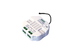
The Aeon Labs Micro Illuminator is a Z-Wave light dimmer specifically used to enable Z-Wave command and control (on/off/dim) for existing in-wall dimmers. The wireless module is powered from the mains supply and is a three-wire design which requires a neutral connection. In the event of power failure, non-volatile memory retains all programmed information relating to the units operating status.
Prepare for Installation / Reset
Please read the user manual before installing the product.
In order to include (add) a Z-Wave device to a network it must be in factory default state. Please make sure to reset the device into factory default. You can do this by performing an Exclusion operation as described below in the manual. Every Z-Wave controller is able to perform this operation however it is recommended to use the primary controller of the previous network to make sure the very device is excluded properly from this network.
Safety Warning for Mains Powered Devices
ATTENTION: only authorized technicians under consideration of the country-specific installation guidelines/norms may do works with mains power. Prior to the assembly of the product, the voltage network has to be switched off and ensured against re-switching.
Installation
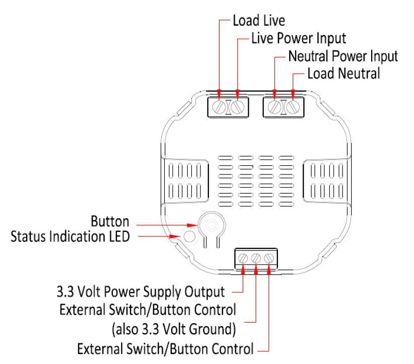
The device is designed for a 3 wire system which requires a neutral connection. The module is powered from the main supply.
The schematic below shows how to wire the actuator. The power supply and the appliance are connected by the Load, Power Input and Neutral connectors. The 3.3 Volt and External Switch connectors are for external switching.
After the electrical installation the device has to be implemented in the Z-Wave Network.
Inclusion/Exclusion
On factory default the device does not belong to any Z-Wave network. The device needs to be added to an existing wireless network to communicate with the devices of this network. This process is called Inclusion.
Devices can also be removed from a network. This process is called Exclusion. Both processes are initiated by the primary controller of the Z-Wave network. This controller is turned into exclusion respective inclusion mode. Inclusion and Exclusion is then performed doing a special manual action right on the device.
Inclusion
To include the Aeon Labs Micro Illuminator with your Z-Wave controller simple bring it in the inclusion-mode and click the Inclusion/Exclusion button at the Aeon Labs Micro Illuminator once. Alternatively you can use the external switch by quickly pressing it six times. If the Aeon Labs Micro Illuminator was successfully included to a Z-Wave network, the Status Indication LED will either be solid on or off (depending on if the switch is on or off) 10 seconds after the button was last pressed.Exclusion
To include the Aeon Labs Micro Illuminator with your Z-Wave controller simple bring it in the inclusion-mode and click the Inclusion/Exclusion button at the Aeon Labs Micro Illuminator once. Alternatively you can use the external switch by quickly pressing it six times. If the Aeon Labs Micro Illuminator was successfully included to a Z-Wave network, the Status Indication LED will either be solid on or off (depending on if the switch is on or off) 10 seconds after the button was last pressed.Product Usage
The dimmer is operated by an external switch/button or wireless. The click on the switch sets the dimmer on or off. To have the dimming function simple hold the button pushed until your desired level. The dimmer insert memorizes the last lighting level and switches automatically to the same level.
Node Information Frame
The Node Information Frame (NIF) is the business card of a Z-Wave device. It contains information about the device type and the technical capabilities. The inclusion and exclusion of the device is confirmed by sending out a Node Information Frame. Beside this it may be needed for certain network operations to send out a Node Information Frame. To issue a NIF execute the following action:
A single click at the Inclusion/Exclusion switch sends a Node Information Frame.
Quick trouble shooting
Here are a few hints for network installation if things dont work as expected.
- Make sure a device is in factory reset state before including. In doubt exclude before include.
- If inclusion still fails, check if both devices use the same frequency.
- Remove all dead devices from associations. Otherwise you will see severe delays.
- Never use sleeping battery devices without a central controller.
- Dont poll FLIRS devices.
- Make sure to have enough mains powered device to benefit from the meshing
Association - one device controls an other device
Z-Wave devices control other Z-Wave devices. The relationship between one device controlling another device is called association. In order to control a different device, the controlling device needs to maintain a list of devices that will receive controlling commands. These lists are called association groups and they are always related to certain events (e.g. button pressed, sensor triggers, ...). In case the event happens all devices stored in the respective association group will receive the same wireless command wireless command, typically a 'Basic Set' Command.
Association Groups:
| Group Number | Maximum Nodes | Description |
|---|---|---|
| 1 | 5 | Status Reports |
Configuration Parameters
Z-Wave products are supposed to work out of the box after inclusion, however certain configuration can adapt the function better to user needs or unlock further enhanced features.
IMPORTANT: Controllers may only allow configuring signed values. In order to set values in the range 128 ... 255 the value sent in the application shall be the desired value minus 256. For example: To set a parameter to 200 it may be needed to set a value of 200 minus 256 = minus 56. In case of a two byte value the same logic applies: Values greater than 32768 may needed to be given as negative values too.
Parameter 1: Type of Sensor Report
Defines the value type to be sent as Sensor Report. Size: 1 Byte, Default Value: 00
| Setting | Description |
|---|---|
| 00 | Power |
| 01 | Voltage |
Parameter 2: Blinking Behavior
This is a double byte value. The LSB defines the total time the device need to blink. The value if set in seconds. The MSB defines the on/off interval of the blinking. The unit is 0.1 s. Size: 2 Byte, Default Value: 0000
| Setting | Description |
|---|
Parameter 80: Notification on Status Change
Defines the automated status notification of an associated device when status changes Size: 1 Byte, Default Value: 00
| Setting | Description |
|---|---|
| 00 | Deactivated |
| 01 | Hail sent |
| 02 | BASIC Report Sent |
Parameter 90: Disables Function of automated sending of a Report triggered by minimal change of value.
Size: 1 Byte, Default Value: 00
| Setting | Description |
|---|---|
| 00 | Disabled |
| 01 | Enabled |
Parameter 91: Minimum Change to send Report (Watt)
The value represents the minimum change in Wattage for a Report to be sent . Size: 2 Byte, Default Value: 0032
| Setting | Description |
|---|---|
| 00 - 3500 | Value in Watt |
Parameter 92: Minimum Change to send Report (%)
The value represents the minimum change in Wattage Percent for a report to be sent Size: 1 Byte, Default Value: 0a
| Setting | Description |
|---|---|
| 00 - 100 | Percentage |
Parameter 101: Report type send in Reporting Group 1
Defines the type of report sent for the Reporting Group 1. Size: 4 Byte, Default Value: 00000008
| Setting | Description |
|---|---|
| Byte 1: 00000100 | MultiSensor Report |
| Byte 1: 00001000 | Meter Report for Watt |
| Byte 1: 00010000 | Meter Report for kWh |
Parameter 102: Report Type send in Reporting Group 2
Defines the type of report sent for the Reporting Group 2. Size: 4 Byte, Default Value: 00000000
| Setting | Description |
|---|---|
| Byte 1: 00000100 | MultiSensor Report |
| Byte 1: 00001000 | Meter Report for Watt |
| Byte 1: 00010000 | Meter Report for kWh |
Parameter 103: Report Type send in Reporting Group 3
Defines the type of report sent for the Reporting Group 3. Size: 4 Byte, Default Value: 00000000
| Setting | Description |
|---|---|
| Byte 1: 00000100 | MultiSensor Report |
| Byte 1: 00001000 | Meter Report for Watt |
| Byte 1: 00010000 | Meter Report for kWh |
Parameter 111: Send Interval for Reporting Group 1
Defines the time interval when the defined report of Reporting Group 1 is sent out. Size: 4 Byte, Default Value: 000002d0
| Setting | Description |
|---|---|
| 00 - ffff | Seconds |
Parameter 112: Send Interval for Reporting Group 2
Defines the time interval when the defined report of Reporting Group 2 is sent out. Size: 4 Byte, Default Value: 000002d0
| Setting | Description |
|---|---|
| 00 - ffff | Seconds |
Parameter 113: Send Interval for Reporting Group 3
Defines the time interval when the defined report of Reporting Group 3 is sent out. Size: 4 Byte, Default Value: 0000ffff
| Setting | Description |
|---|---|
| 00 - ffff | Seconds |
Technical Data
| Dimensions | 0.0510000x0.0510000x0.0180000 mm |
| Weight | 40 gr |
| Hardware Platform | ZM3102 |
| EAN | 1220000011489 |
| IP Class | IP 20 |
| Voltage | 230 |
| Device Type | Light Dimmer Switch |
| Generic Device Class | Multilevel Switch |
| Specific Device Class | Routing Multilevel Switch |
| Firmware Version | 01.18 |
| Z-Wave Version | 02.4e |
| Certification ID | ZC08-13030004 |
| Z-Wave Product Id | 0086.0003.000d |
| Frequency | Europe - 868,4 Mhz |
| Maximum transmission power | 5 mW |
Supported Command Classes
- Basic
- Association
- Switch Multilevel
- Switch All
- Meter
- Configuration
- Sensor Multilevel
- Manufacturer Specific
- Version
Explanation of Z-Wave specific terms
- Controller — is a Z-Wave device with capabilities to manage the network. Controllers are typically Gateways,Remote Controls or battery operated wall controllers.
- Slave — is a Z-Wave device without capabilities to manage the network. Slaves can be sensors, actuators and even remote controls.
- Primary Controller — is the central organizer of the network. It must be a controller. There can be only one primary controller in a Z-Wave network.
- Inclusion — is the process of adding new Z-Wave devices into a network.
- Exclusion — is the process of removing Z-Wave devices from the network.
- Association — is a control relationship between a controlling device and a controlled device.
- Wakeup Notification — is a special wireless message issued by a Z-Wave device to announces that is able to communicate.
- Node Information Frame — is a special wireless message issued by a Z-Wave device to announce its capabilities and functions.