Aeotec
Recessed Door Sensor
SKU: AEO_ZW089


Quickstart
This is a
Single click the Z-Wave button on the device with a small pin to include or exclude the device. Clicking the little button behind the battery cover will wake up the device and keep it awake.
Important safety information
Please read this manual carefully. Failure to follow the recommendations in this manual may be dangerous or may violate the law. The manufacturer, importer, distributor and seller shall not be liable for any loss or damage resulting from failure to comply with the instructions in this manual or any other material. Use this equipment only for its intended purpose. Follow the disposal instructions. Do not dispose of electronic equipment or batteries in a fire or near open heat sources.Product Description
Recessed Door Sensor is a new small and compact Z-Wave sensor with the size of 2.5*7 cm (main body), that tells you and your Z-Wave network if a door is open or closed. It is nearly invisible, as the sensor is installed with the help of a slight drill hole hidden away on the top of your door. Installing Recessed Door Sensor is easy, as you only have to add it to your home"s network activating its battery and associating it with your Z-Wave system. When included securely the device is able to accept secure commands and to send secure commands to other devices.
Installation
The sensor is invisibly installed, so it sits within a door and its frame to provide all the information needed by a Z-Wave system for security, safety and ambiance.
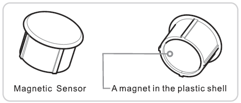
The Recessed Door Sensor is comprised of two parts: the larger Main Sensor and the smaller Magnetic Sensor. Both of them are to be installed for proper use.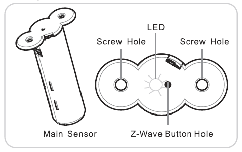
Prepare the Main Sensor
The first Step in installing your Recessed Door Sensor is to activate the Main Sensor.
1. Using a slot-head scrwedriver, remove the Main Sensor"s lid by pressing gently against its exposed connector.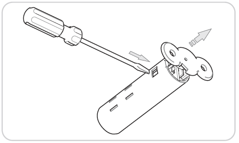
2. Seperate the Main Sensors"s two sections by first removing its lid and then removing its internal components.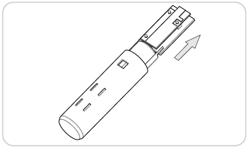
3. Remove the clear battery insulator by pulling it away from the Main Sensor.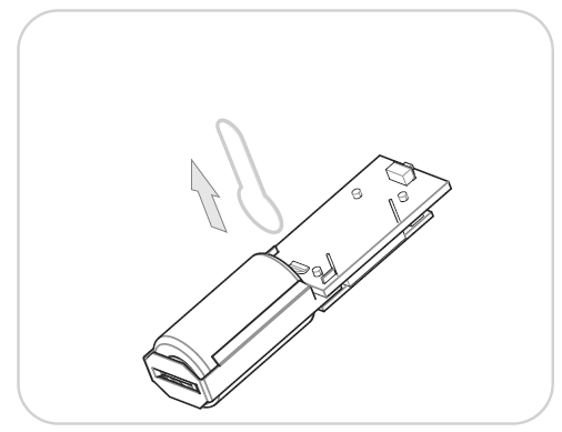
4. With the battery insulator removed, reinsert the internal components into the enclosure before reattaching its lid. Ensure that the Main Sensor"s button aligns with the button hole of its lid.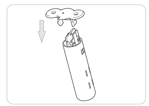
Install the Main Sensor and Magnetic Sensor
Before beginning it is important to select a suitable position for your Recessed Door Sensor. Comply with the the following hints:
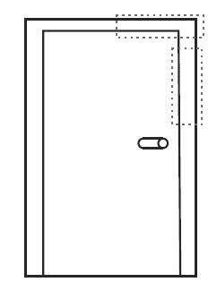
- Install at the top or the side of a door.
- Position away from metal that could interfere with the sensor"s magnetic funtionality. This includes your door blade, handle or lock mechanism.
- Install in a suitable location to ensure a clear (at least 1mm) seperation when the door is closed.
- Position exactly counterpart to the Magnetic Sensor.
Step 1:
Prepare a space for the Main Sensor by drilling a hole into your doorframe using a 19mm wide drill bit. The hole should be 65mm deep.
Step 2:
Drill a corresponding hole in your door. The hole should be 15mm deep and 19mm wide. The position of the hole should allign exactly counterpart to hole in the door frame.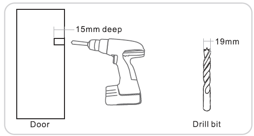
Step 3:
Insert the Main Sensor into the hole you created in the doorframe and fix it with two screws.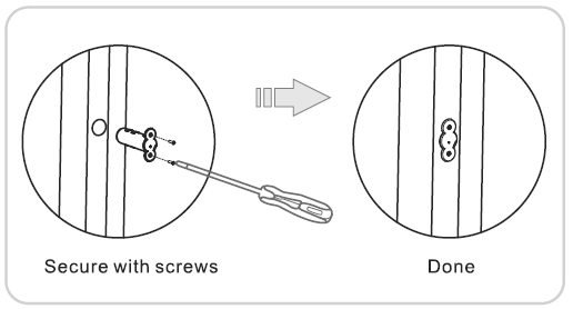
Step 4:
Place a small amount of white glue (PVA) inside the hole you created and place the Magnetic Sensor inside. Insert it by tapping gently on it with a rubber hammer.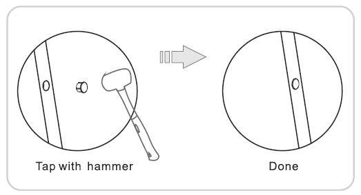
The gap between the two parts of your sensor must be at least 1 mm. Re-Affix the Sensors, if it doesn"t fit.
Product Usage
The Door Sensor reports the status of your door (open / closed) to a Z-Wave gateway or controller. The sensor will send radio signals up to 5 associated Z-Wave devices within 2 two association groups in its own Z-Wave network.
| Reset to factory default | XXXResetDescription |
| Inclusion | Make sure that your Z-Wave Controller is in the Inclusion-/Exclusion-Mode. Single click the Z-Wave button on the device with a small pin to include or exclude the device. A successful Inclusion/Exclusion lights up the sensor LED for a few seconds. |
| Exclusion | Make sure that your Z-Wave Controller is in the Inclusion-/Exclusion-Mode. Single click the Z-Wave button on the device with a small pin to include or exclude the device. A successful Inclusion/Exclusion lights up the sensor LED for a few seconds. |
| NIF | A single click on the Z-Wave button sends a Node Information Frame. |
| Wakeup | A single click on the Z-Wave button will wakes up the device and keep it awake. |
| Protection | XXXProtection |
| FirmwareUpdate | XXXFirmwareUpdate |
| SetAssociation | XXXSetAssociation |
Association Groups:
| Group Number | Maximum Nodes | Description |
|---|---|---|
| 1 | 5 | receive Basic Set/ Sensor Binary Report, when the state |
| 2 | 5 | receive the Battery Low Warning Report and Battery Report |
Configuration Parameters
Parameter 1: sensor binary report for magnet switch
value, which is send when Magnet switch open/close Size: 1 Byte, Default Value: 0
| Setting | Description |
|---|---|
| 0 | open = 0; close = 255 |
| 1 | open = 255; close = 0 |
Parameter 3: basic set for magnet switch
value, which is send when Magnet switch open/close Size: 1 Byte, Default Value: 0
| Setting | Description |
|---|---|
| 0 | open = 0; close = 255 |
| 1 | open = 255; close = 0 |
Parameter 101: low battery voltage check function
parameter defines, if battery check function is possible, when battery is below warning voltage Size: 1 Byte, Default Value: 0
| Setting | Description |
|---|---|
| 0 | Disable |
| 1 | Enable |
Parameter 111: battery low check Interval time
minimum battery low check Interval time is 4 minutes Size: 4 Byte, Default Value: 86640
| Setting | Description |
|---|---|
| 0 - 4294967295 | in seconds |
Parameter 121: Command to Associated Nodes
To set which command will be sent to the associated nodes when the magnet switch is triggered. Size: 4 Byte, Default Value: 256
| Setting | Description |
|---|---|
| 16 | Sensor binary |
| 256 | Basic Set |
Parameter 252: Lock Configuration
Lock/ unlock all configuration parameters. Size: 1 Byte, Default Value: 0
| Setting | Description |
|---|---|
| 0 | Unlock |
| 1 | Lock |
Parameter 254: Device Tag
Size: 2 Byte, Default Value: 0000
| Setting | Description |
|---|
Parameter 255: Reset to default factory setting
Size: 4 Byte, Default Value: 0
| Setting | Description |
|---|---|
| 1 | Resets all configuration parameters to default setting. |
| 1431655765 | Reset the product to default factory setting and be excluded from the Z-wave network. |
Technical Data
| Dimensions | 0.0410000x0.0635000x0.0190000 mm |
| Weight | 30 gr |
| Hardware Platform | ZM3102 |
| EAN | 1220000012721 |
| IP Class | IP 20 |
| Battery Type | 1 * CR2 |
| Firmware Version | 01.0c |
| Z-Wave Version | 03.5c |
| Certification ID | ZC10-14120011 |
| Z-Wave Product Id | 0x0086.0x0002.0x0059 |
| Frequency | Europe - 868,4 Mhz |
| Maximum transmission power | 5 mW |