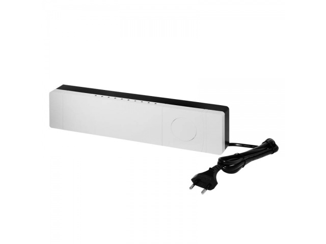
Danfoss
Hydronic Controller 5
SKU: DANEHC5
Quickstart
This is a
Press the button
Important safety information
Please read this manual carefully. Failure to follow the recommendations in this manual may be dangerous or may violate the law. The manufacturer, importer, distributor and seller shall not be liable for any loss or damage resulting from failure to comply with the instructions in this manual or any other material. Use this equipment only for its intended purpose. Follow the disposal instructions. Do not dispose of electronic equipment or batteries in a fire or near open heat sources.Product Description
Danfoss Link HC is part of the wireless control system for heating systems in residential buildings, controlled by the central controller Danfoss Link CC. The Danfoss Link HC enables the control of of hot water underfloor heating systems. The system offers a wide range of Extended functions for optimum comfort and energy saving and also allows for the individual room temperature control.
The Danfoss Link HC includes the following Functions: 2-way radio transmission, up to 5 short-circuit-proof outputs for 24 V NC or NO actuators, relays for the pumps and pumps Boiler control, self-diagnostic program, Contact for the absence function, Heating/Cooling function, regulation according to the ON/OFF or PWM principle (pulse width modulation) etc. The system can be configured from up to three Danfoss Link HC up to 30 outputs for larger systems can be connected to the system.
The Danfoss Link HC includes the following Functions: 2-way radio transmission, up to 5 short-circuit-proof outputs for 24 V NC or NO actuators, relays for the pumps and pumps Boiler control, self-diagnostic program, Contact for the absence function, Heating/Cooling function, regulation according to the ON/OFF or PWM principle (pulse width modulation) etc. The system can be configured from up to three Danfoss Link HC up to 30 outputs for larger systems can be connected to the system.
Installation
Hydronic Controller
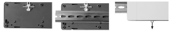
Mount the Hydronic Controller horizontally upright.
Mounting on Wall: Remove the front and side covers. Mount the controller with screws and plugs.
24V Actuators
- Connect the two actuator cables to the output (4).
- Fix the cable (8).
Note! NC (Normally Closed) configuration of the actuator output is preset.
Relays for pump and heater control
- Connect the pump and heater control cables to the respective output (2/3).
- Fix the cable (7).
Note! The pump and heater relays are floating contacts and can therefore NOT be used for a direct power supply can be used. The maximum load is 230 V and 8 A/2 A.
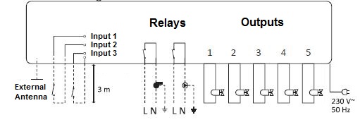
Power supply
Connect all actuators before connecting the device to the power supply! After you have installed all actuators, pump and heater controls as well as other inputs, connect the power plug of the Hydronic Controller to a 230V power source.
Note! If the mains plug is disconnected from the power supply cable during installation, make sure that it is reconnected in accordance with the applicable guidelines.
Note! If the mains plug is disconnected from the power supply cable during installation, make sure that it is reconnected in accordance with the applicable guidelines.
External antenna (not included)
An external antenna is used as an amplifier if the transmission is interrupted by the use of an external antenna in a large buildings, heavy constructions or metal barriers, e. g. if the Hydronic controller is installed in a metal cabinet or box.
- Break out the plastic plug above the antenna connection of the Hydronic Conntrollers.
- Connect the external antenna (A).
- Position the antenna on the other side of the obstacle.
Product Usage
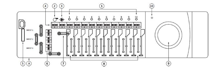
1. Output LED‘s
2. Boiler Relay
3. Pump Relay
4. Output 1 - 5
5. Front cover release button
6. Input 1 - 3 (not use)
7. Cable attachment for relay
8. Cable attachment for outputs
9. Connect button
10. Power - LED
A. External antenna
LED indicator
Green ... The Hydronic controller has been added to a Z-Wave network.
Green flashing ... The Hydronic Controller has NOT been connected to a Z-Wave network.
Fast green flashing ... Connection to the network is established. This process can also be carried out so quickly that no flashing to is recognizable.
Red ... The instrument is reset to the factory settings.
Red flashing ... Error mode for one or more thermostats.
Output LED 1 - 5
Off ... The valve for the chain is closed.
Green ... The valve for the chain is open.
Green flashing ... There is an error in the chain or an indication is required.
| Reset to factory default | - Disconnect the Hydronic Controller from the power supply.
- Wait until the green LED goes out.
- Press and hold the installation button (9) and hold it down.
- Reconnect the power supply while holding down the installation button.
- Release the button as soon as the power LED (10) lights up. |
| Inclusion | Press the button |
| Exclusion | Press the button |
| NIF | XXXNIF |
| Wakeup | XXXWakeupDescription |
| Protection | XXXProtection |
| FirmwareUpdate | XXXFirmwareUpdate |
| SetAssociation | XXXSetAssociation |
Association Groups:
| Group Number | Maximum Nodes | Description |
|---|---|---|
| 1 | 1 | Lifeline |
Configuration Parameters
Parameter 1: Valve Type (root only)
Size: 1 Byte, Default Value: 0
| Setting | Description |
|---|---|
| 0 | Normally closed |
| 1 | Normally open |
Parameter 2: Heat Load Strategy (root only)
Size: 0 Byte, Default Value: 0
| Setting | Description |
|---|---|
| 0 | Stacking |
| 1 | Spreading |
Parameter 3: PWM period
Size: 1 Byte, Default Value: 2
| Setting | Description |
|---|---|
| 0 | Short (15 min) |
| 1 | Medium (30 min) |
| 2 | Long (60 min) (default) |
Technical Data
| Dimensions | 325 x 78 x 47 mm |
| Weight | 661.52 gr |
| Hardware Platform | ZM3102 |
| EAN | 5702425190513 |
| IP Class | IP 30 |
| Voltage | 230 V |
| Load | 35 VA |
| Device Type | Barrier Operator |
| Generic Device Class | Thermostat |
| Specific Device Class | Thermostat General V2 |
| Network Operation | Not Z-Wave+ |
| Z-Wave Version | 4.55.00 |
| Certification ID | ZC08-16010005 |
| Z-Wave Product Id | 0x0002.0x0248.0xA040 |
| Frequency | Europe - 868,4 Mhz |
| Maximum transmission power | 5 mW |