Danfoss
Z-Wave Radiator Valve Thermostat
SKU: DAN_LIVC_RAK
Quickstart
This is a
Important safety information
Please read this manual carefully. Failure to follow the recommendations in this manual may be dangerous or may violate the law. The manufacturer, importer, distributor and seller shall not be liable for any loss or damage resulting from failure to comply with the instructions in this manual or any other material. Use this equipment only for its intended purpose. Follow the disposal instructions. Do not dispose of electronic equipment or batteries in a fire or near open heat sources.Product Description
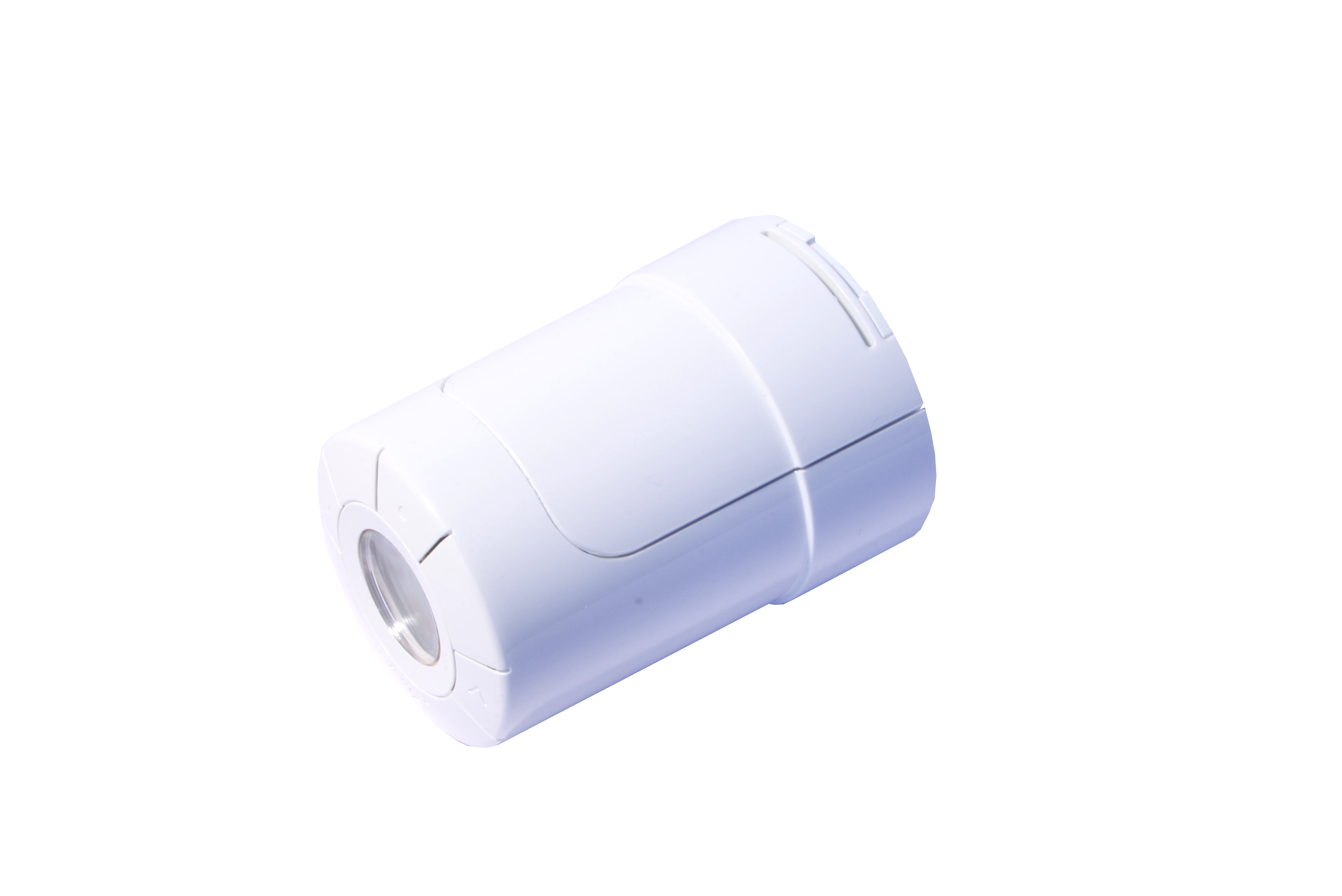
Living Connect is a Z-Wave controlled electronic radiator thermostat. It is mounted on wall heating valves and controls them by a motor. The device accepts a setpoint that is either set manually using buttons on the device or wirelessly using Z-Wave. Afterwards, the device will regulate the warm water supply to the wall radiator and compare the detected temperature to ensure, that the temperature in the room is kept at the desired level. A small LCD panel on the device displays the setpoint temperature on request.
The device has an internal scheduler, that allows to define up to 9 setpoints for up to 7 week days. Once programmed, these setpoints will be activated without any further manual or wireless interaction. Beside setting a desired temperature the device will support special heating schemes, such as energy saving and frost protection and intelligent functions such as detection of open windows or a valve training function to ensure that valves are still operational after longer periods.
The living connect can be mounted to valves with standard M30x1.5 connector or RA2000 (Danfoss snap in).
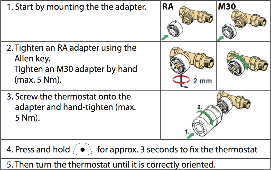
Installation
Installation
The device can be adjusted to the room size. Three room sizes are known. The default size is P1. To change the assumed room size press (p) for 3 seconds to enter management mode (M in display). Press (v) until a "P" is displayed in the LCD display. Hit the (o) button. Now select 1, 2 or 3 using the arrow keys and exit with (o).
RemovalTo remove the thermostat, insert an appropriate tool in the hole in the thermostat"s battery chamber (see illustration). Keeping the tool in position, turn the entire thermostat anticlockwise until it is completely unscrewed.
Product Usage
The Danfoss device is operated by wireless commands from a Z-Wave controller. It is operated in two different modes:
- Direct setting of Temperature Set Point by Controller. (Attention: There may be a delay in execution of a setpoint command due to the wakeup interval of the device. If the setpoint is to be changed at e.g. 16.00 and the wakeup interval is 15 minutes, make sure to send the command latest at 15.45)
- Downloading of a whole weekly schedule into the device that will then regulate the heat independent of the controller. The device is capable holding a complete schedule with up to 9 different setpoints for each individual week day. The device will calculate the best time to start heating up or heating down.
The actual temperature setpoint is shown in the LCD display and can be overwritten by using the arrow keys on the device. This overwriting is temporary and only valid until the next change of the temperature setpoint (either triggered from external wireless command or from the internal downloaded schedule) becomes active.
The device will also recognize an open window (sudden temperature drop within short period of time) and turn down the heat for 30 minutes to save energy.
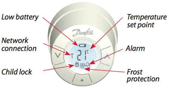
Local LCD DisplayThe local LCD display gives information about the status of the device
The Thermostat allows to check the link quality to the controller device. Press the middle button (o) for 3 seconds until M is displayed. Select "LI" in display using the arrow keys, then confirm the link test with the middle button. A blinking antenna symbol indicates the link test. If the antenna symbol keeps flashing after about 3 seconds there is a problem with the wireless connection. If the antenna symbol stops flashing, the link quality is sufficient. A successfull link test will also terminate the exception mode described below.
Known Problems in Z-Wave Networks: This device is sleeping and wakes up regularly. When waking up the device needs a wireless connection to the controller to get clock and heating schedule updates if needed. If no wireless connection to the controller can be found the device will enter an exception mode indicated by a flashing bell in conjunction with flashing antenna symbol on the LCD display. To exit this exception mode as soon as possible the device tries to reestablish a wireless connection by applying the so-called "Lost" procedure defined by Z-Wave with the help of a Static Update Controller (SUC) in the network. In case of success the execption mode is terminated. In case of failure - e.g. because the controller is still shut off - the device will remain in the exception mode and repeats the "Lost" process. This drains the battery very fast. To avoid this situation make sure the following requirements are made: (a) the thermostat has a stable direct wireless connection to the controller or (b) there is a static controller serving as SUC in the Z-Wave network and there is a valid route between the device and this SUC.
The device applies multiple technologies to extend battery life. It is combining multi commands to a single command and adapt its behavior to the capabilities of the network controller. Make sure to use Danfoss Living connects only with Z-Wave controllers fully implementing all battery life time extention methods recommended by Danfoss. All controllers based on Z-Wave.Me software (e.g. RaZberry) fully support these methods.
When the battery level is low, the alarm bell icon flashes and the display will flash 8 times an hour between 19 and 22 hrs. If the battery goes flat, the system switches automatically to frost protection mode.
| Reset to factory default | Remove the battery cover and take out one battery. Press and hold the (o) button for about 10 secs while reinserting the battery. The device will go into management mode. |
| Inclusion | Click on the middle button will confirm inclusion or exclusion and wakeup the device for wireless communication. A long push for 3 seconds on the middle buttons enters and leaves the management mode indicated by a "M". |
| Exclusion | Click on the middle button will confirm inclusion or exclusion and wakeup the device for wireless communication. A long push for 3 seconds on the middle buttons enters and leaves the management mode indicated by a "M". |
| NIF | Click on the middle button will send out a Node Information Frame (if not in exception mode). |
| Wakeup | Click on the middle button will wakeup the device for wireless communication (if not in exception mode). |
| Protection | XXXProtection |
| FirmwareUpdate | XXXFirmwareUpdate |
| SetAssociation | XXXSetAssociation |
Association Groups:
| Group Number | Maximum Nodes | Description |
|---|---|---|
| 1 | 1 | Target for Wakeup and Override Notifications |
Technical Data
| Dimensions | 0.0510000x0.0510000x0.0710000 mm |
| Weight | 113 gr |
| Hardware Platform | ZM3102 |
| Battery Type | 2 * AA |
| Firmware Version | 02.33 |
| Z-Wave Version | 02.43 |
| Certification ID | ZC08-13120001 |
| Z-Wave Product Id | 0002.0005.0003 |
| Frequency | Europe - 868,4 Mhz |
| Maximum transmission power | 5 mW |