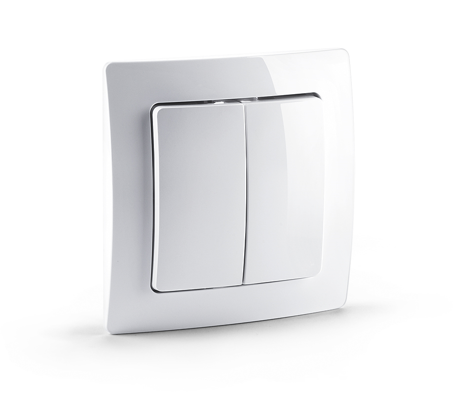
Devolo
Scene Switch
SKU: DEVE9359


Quickstart
This is a
After the first action you can further manage and configure the wall controller using the management mode. To activate this management mode push all four buttons for one second simultaneously (green blinks slowly). The buttons will have different functions then (see Installation Guidelines).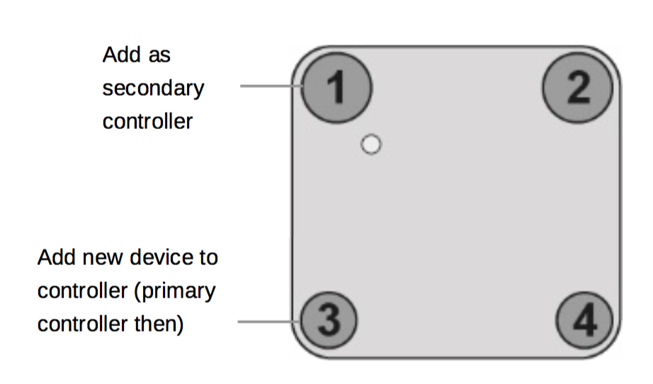
Attention:For convenience reasons some special short cut apply IF and only IF the KFOB is the primary controller of the network: The first device included into a button group will define the commands sent out by this group regardless of the default value of the configuration parameters 11-14. If the device is a door lock the button group will turn into door lock control (value=7). For dimmers and motor controls the value changes into Multilevel Switch Control (value=1). All other devices will turn the button group into Basic control (value=2). All configuration values can be changed if needed. When KFOB is primary controller the very first device included will be automatically put into button group A and the command set will change according to the rules just mentioned. All other devices need ot be put in button groups manually.
Important safety information
Please read this manual carefully. Failure to follow the recommendations in this manual may be dangerous or may violate the law. The manufacturer, importer, distributor and seller shall not be liable for any loss or damage resulting from failure to comply with the instructions in this manual or any other material. Use this equipment only for its intended purpose. Follow the disposal instructions. Do not dispose of electronic equipment or batteries in a fire or near open heat sources.What is Z-Wave?
Z-Wave is the international wireless protocol for communication in the Smart Home. This device is suited for use in the region mentioned in the Quickstart section.
Z-Wave ensures a reliable communication by reconfirming every message (two-way communication) and every mains powered node can act as a repeater for other nodes (meshed network) in case the receiver is not in direct wireless range of the transmitter.
This device and every other certified Z-Wave device can be used together with any other certified Z-Wave device regardless of brand and origin as long as both are suited for the same frequency range.
If a device supports secure communication it will communicate with other devices secure as long as this device provides the same or a higher level of security. Otherwise it will automatically turn into a lower level of security to maintain backward compatibility.
For more information about Z-Wave technology, devices, white papers etc. please refer to www.z-wave.info.
Product Description
The MT2652 Scene Switch is a Z-Wave device that can both control other Z-Wave devices and activate scenes. Although it is controlling other devices, the Wall Controller cannot act as Z-Wave network controller (primary or secondary) and will always need a Z-Wave network controller to be included into a Z-Wave network. The device can be used in different modes that are selected by configuration parameters:
Control of groups of other Z-Wave devices using ‘ON‘, ‘OFF‘ and Dim commands.
Activation of predefined scenes in Gateways or other Z-Wave devices.
This device support secure communication when included by a controller that also supports secure communication.
Prepare for Installation / Reset
Please read the user manual before installing the product.
In order to include (add) a Z-Wave device to a network it must be in factory default state. Please make sure to reset the device into factory default. You can do this by performing an Exclusion operation as described below in the manual. Every Z-Wave controller is able to perform this operation however it is recommended to use the primary controller of the previous network to make sure the very device is excluded properly from this network.
Reset to factory default
This device also allows to be reset without any involvement of a Z-Wave controller. This procedure should only be used when the primary controller is inoperable.
Use this procedure only if the primary controller is missing or otherwise inoperable. (1) Turn the device into Management Mode by keeping all four buttons pushed for 5 seconds, (2) click on Button 3, (3) keep button 4 pushed for 4 seconds.
Safety Warning for Batteries
The product contains batteries. Please remove the batteries when the device is not used. Do not mix batteries of different charging level or different brands.
Installation
The device can be mounted on every flat surface either using the screws provided or the double sided tape provided as well.
To atviate the device and access hte four buttons independently for management mode operations please remove the rocker using a screw driver or simply the fingers. Push hard on one corner and lift the other corner so that the rocker will unsnap.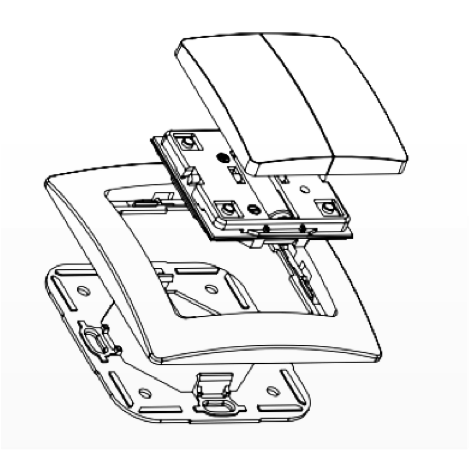
- Operation Mode: This is the mode where the device is controlling other Z-Wave devices or is activating scenes.
- Management Mode: The device is turned into the management mode by pushing all four buttons for one second together. A blinking green LED indicates the management mode. In the management mode the buttons of the device have different functions. If no further action is performed, the device will turn back to the normal mode after 10 sec. Any management action terminates the management mode as well.
- Button 1 - Inclusion/Exclusion: Every inclusion or exclusion attempt is confirmed by hitting this button. Single Click is used for standard inclusion and exclusion, double click is used for network wide inclusion. With this operation the device can be included into a Z-Wave Network from any physical location in the network. This requires a primary controller supporting network wide inclusion. This mode lasts for 20 seconds and stops automatically. Any button press stops the mode as well.
- Button 2 - Sends Node Information Frame and Wake up Notification. (see explanation below)
- Button 3 - Activates the primary controller management menu. The following sub menu items are available:
- Button 3 followed by short click of button 1: Start Secure Inclusion
- Button 3 followed by short click of button 2: Start Unsecure Inclusion
- Button 3 followed by short click of button 3: Start Exclusion
- Button 3 followed by short click of button 4: Start Primary Handover
- Button 3 followed by pushing button 4 for 5 seconds: Factory Default Reset. After clicking on button 3 keep button 4 pushed for 4 seconds
- Button 4 - Enters into Association mode to assign target devices to one of the four associations. Refer to the manuals section about association for more information how to set and unset association groups.
- Button 1: Include as secondary controller
- Button 2: Include as secondary controller - non secure
- Button 3: Include new device into wall controllers network
- Button 4: Include new device into wall controllers network - non secure
Inclusion/Exclusion
On factory default the device does not belong to any Z-Wave network. The device needs to be added to an existing wireless network to communicate with the devices of this network. This process is called Inclusion.
Devices can also be removed from a network. This process is called Exclusion. Both processes are initiated by the primary controller of the Z-Wave network. This controller is turned into exclusion respective inclusion mode. Inclusion and Exclusion is then performed doing a special manual action right on the device.
Inclusion
Place your primary controller in inclusion mode by following the manufacturer‘s instructions, then activate inclusion on the wall controller by pressing any one of the four buttons for one second. Inclusion mode is indicated by the red/green blinking of the LEDs until the timeout occurs after 10 seconds.Exclusion
Re-Inclusion and Exclusion are performed by pushing button 1 in management mode. Pushing all four buttons for 5 sec. turns the device into management mode (indicated by blinking green LED).Product Usage
Depending on the button mode and operating modes configured using the configuration parameters the key fob can be used in different ways.
Button modes:
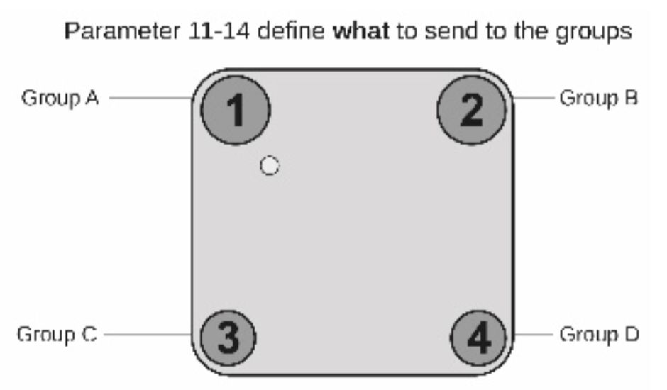
4 Groups are controlled with single button (parameter 1/2 = 0) The four buttons 1-4 control one single control group each: 1->A, 2->B, 3->C, 4->D. Single click turns devices in the control group on, double click turns them off. Click and hold can be used for dimming.
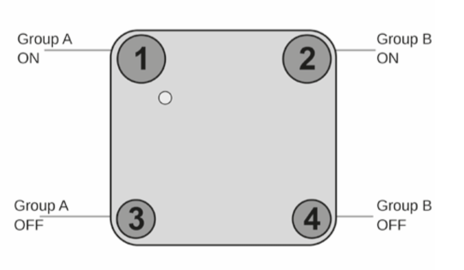
2 Groups are controlled with two buttons (parameter 1/2 = 1) The buttons 1 and 3 control the control group A (button one turns on, button three turns off), the buttons 2 and 4 control the control group B (button two turns on, button four turns off). In case dimmers are controlled, holding down the larger button will dim up, holding down the smaller button will dim down the load. Releasing the button will stop the dimming function.
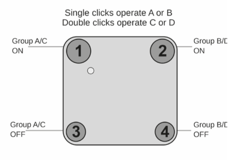
4 Groups are controlled with two buttons and double click (parameter 1/2 = 2) This mode enhances the previous mode and allows to control two further control groups C and D using double clicks.
Operating modes:
The devices supports 8 different operating modes - this means the kind of command sent out when pushing a button. Operating modes either directly control other devices or they issue various scene activation commands to a central controller. Operating modes for direct device control are:- Direct Control of associated devices with On/Off/Dim commands (parameter 11...14 = 1). Devices are controlled using Basic Set On/Off commands and Switch-Multilevel Dim Start/Stop. This mode implements communication pattern 7.
- Direct Control of associated devices with only On/Off commands (parameter 11...14 = 2). Devices are controlled using only Basic Set On/Off commands. On dimming Up event On is sent, on dimming Down Off is sent. This mode also implements communication pattern 7.
- Switch All commands (parameter 11...14 = 3) In this mode a all neighboring devices will receive Switch-All Set On/Off command and interpret it according to their membership in Switch-All groups. This mode implements communication pattern 7.
- Direct Control of Devices in proximity (parameter 11...14 = 6). Basic Set and Switch-Multilevel Dim commands are sent to a device in proximity (50...100 cm) from the Fob. Attention: In case there are more than one Z-Wave devices nearby all these devices may be switched. For this reason the proximity function should be handled with care. This mode implements communication pattern 7
- Door Lock Control (parameter 11...14 = 7) This mode allows direct control (open/close) of electronic door locks using secure communication. The mode implements communication pattern 7.
- Direct Activation of preconfigured scenes (parameter 11...14 = 5) Associated devices in an association group are controlled by individual commands defines by Z-Wave command class ?Scene Controller Configuration?. This mode enhances mode Direct Control of associated devices with On/Off/Dim commands and implements communication patterns 6 and 7. Please turn the button mode to "separate" to allow different a scene ID on every button.
- Scene Activation in IP Gateway (parameter 11...14 = 4) If configured correctly the buttons can trigger a scene in a gateway. The scene number triggered is a combination of the group number and the action performed on the button and has always two digits. The group number defines the upper digit of the scene number, the action the lower digit. The following actions are possible:
- 1 = On
- 2 = Off
- 3 = Dim Up Start
- 4 = Dim Down Start
- 5 = Dim Up Stop
- 6 = Dim Down Stop
Example: Clicking/double clicking the button will issue scene triggers, scene 11 (button 1 click, event on), scene 12 (button double click 1, event off, single button control is used in this example)
- Activation of Central Scenes (parameter 11...14 = 8,Default) Z-Wave Plus introduces a new process for scene activation - the central scene control. Pushing a button and releasing a button send a certain command to the central controller using the lifeline association group. This allows reacting both on button push and button release. This mode implements communication patterns 6 but requires a central gateway supporting Z-Wave Plus.
- Confirmation - green 1 sec
- Failure - red 1 sec
- Button press confirmation - green 1/4 sec
- Waiting for Network Management mode selection - slow green blinks
- Waiting for group selection in Association Set Mode - green fast blink
- Waiting for primary controller function selection - green fast blink
- Waiting for NIF in Association Set Mode - green-red-off blink
Node Information Frame
The Node Information Frame (NIF) is the business card of a Z-Wave device. It contains information about the device type and the technical capabilities. The inclusion and exclusion of the device is confirmed by sending out a Node Information Frame. Beside this it may be needed for certain network operations to send out a Node Information Frame. To issue a NIF execute the following action: Pressing Button 2 in management mode will issue a Node Information Frame.
Communication to a Sleeping device (Wakeup)
This device is battery operated and turned into deep sleep state most of the time to save battery life time. Communication with the device is limited. In order to communicate with the device, a static controller C is needed in the network. This controller will maintain a mailbox for the battery operated devices and store commands that can not be received during deep sleep state. Without such a controller, communication may become impossible and/or the battery life time is significantly decreased.
This device will wakeup regularly and announce the wakeup state by sending out a so called Wakeup Notification. The controller can then empty the mailbox. Therefore, the device needs to be configured with the desired wakeup interval and the node ID of the controller. If the device was included by a static controller this controller will usually perform all necessary configurations. The wakeup interval is a tradeoff between maximal battery life time and the desired responses of the device. To wakeup the device please perform the following action: (1) Turn the device into Management Mode by keeping all four buttons pushed for 5 seconds, (2) click on Button 2.
Quick trouble shooting
Here are a few hints for network installation if things dont work as expected.
- Make sure a device is in factory reset state before including. In doubt exclude before include.
- If inclusion still fails, check if both devices use the same frequency.
- Remove all dead devices from associations. Otherwise you will see severe delays.
- Never use sleeping battery devices without a central controller.
- Dont poll FLIRS devices.
- Make sure to have enough mains powered device to benefit from the meshing
Association - one device controls an other device
Z-Wave devices control other Z-Wave devices. The relationship between one device controlling another device is called association. In order to control a different device, the controlling device needs to maintain a list of devices that will receive controlling commands. These lists are called association groups and they are always related to certain events (e.g. button pressed, sensor triggers, ...). In case the event happens all devices stored in the respective association group will receive the same wireless command wireless command, typically a 'Basic Set' Command.
Association Groups:
| Group Number | Maximum Nodes | Description |
|---|---|---|
| 1 | 10 | Z-Wave Plus Lifeline |
| 2 | 10 | Control Group A, controlled by button 1 or single clicks of buttons 1 and 3 |
| 3 | 10 | Control Group B, controlled by button 2 or single clicks of buttons 2 and 4 |
| 4 | 10 | Control Group C, controlled by button 3 or double clicks of buttons 1 and 3 |
| 5 | 10 | Control Group D, controlled by button 4 or double clicks of buttons 2 and 4 |
Configuration Parameters
Z-Wave products are supposed to work out of the box after inclusion, however certain configuration can adapt the function better to user needs or unlock further enhanced features.
IMPORTANT: Controllers may only allow configuring signed values. In order to set values in the range 128 ... 255 the value sent in the application shall be the desired value minus 256. For example: To set a parameter to 200 it may be needed to set a value of 200 minus 256 = minus 56. In case of a two byte value the same logic applies: Values greater than 32768 may needed to be given as negative values too.
Parameter 1: Button 1 and 3 pair mode
In separate mode button 1 works with Group A, button 3 with Group C. Click is ON, Hold is dimming UP, Double click is OFF, Click-Hold is dimming DOWN. In pair button 1/3 are UP/DOWN correspondingly. Click is ON/OFF, Hold is dimming UP/DOWN. Single clicks works with Group A, double click with Group C. Size: 1 Byte, Default Value: 1
| Setting | Description |
|---|---|
| 0 | Separately |
| 1 | In pair without double clicks |
| 2 | In pair with double clicks |
Parameter 2: Button 2 and 4 pair mode
In separate mode button 2 works with control group B, button 4 with control group D. Click is ON, Hold is dimming UP, Double click is OFF, Click-Hold is dimming DOWN. In pair button B/D are UP/DOWN correspondingly. Click is ON/OFF, Hold is dimming UP/DOWN. Single clicks works with Group B, double click with Group D. Size: 1 Byte, Default Value: 1
| Setting | Description |
|---|---|
| 0 | Separately |
| 1 | In pair without double clicks |
| 2 | In pair with double clicks |
Parameter 11: Command to control Group A
This parameter defines the command to be sent to devices of control group A when the related button is pressed. Size: 1 Byte, Default Value: 8
| Setting | Description |
|---|---|
| 0 | Disable |
| 1 | Switch on/off and Dim (send Basic Set and Switch Multilevel) |
| 2 | Switch on/off only (send Basic Set) |
| 3 | Switch all |
| 4 | Send scenes |
| 5 | Send preconfigured scenes |
| 6 | Control devices in proximity |
| 7 | Control door lock |
| 8 | Central scene to gateway (default) |
Parameter 12: Command to control Group B
This parameter defines the command to be sent to devices of control group B when the related button is pressed. Size: 1 Byte, Default Value: 8
| Setting | Description |
|---|---|
| 0 | Disable |
| 1 | Switch on/off and Dim (send Basic Set and Switch Multilevel) |
| 2 | Switch on/off only (send Basic Set) |
| 3 | Switch all |
| 4 | Send scenes |
| 5 | Send preconfigured scenes |
| 6 | Control devices in proximity |
| 7 | Control door lock |
| 8 | Central scene to gateway (default) |
Parameter 13: Command to control Group C
This parameter defines the command to be sent to devices of control group C when the related button is pressed. Size: 1 Byte, Default Value: 8
| Setting | Description |
|---|---|
| 0 | Disable |
| 1 | Switch on/off and Dim (send Basic Set and Switch Multilevel) |
| 2 | Switch on/off only (send Basic Set) |
| 3 | Switch all |
| 4 | Send scenes |
| 5 | Send preconfigured scenes |
| 6 | Send preconfigured scenes |
| 7 | Control door lock |
| 8 | Central scene to gateway |
Parameter 14: Command to control Group D
This parameter defines the command to be sent to devices of control group D when the related button is pressed. Size: 1 Byte, Default Value: 8
| Setting | Description |
|---|---|
| 0 | Disable |
| 1 | Switch on/off and Dim (send Basic Set and Switch Multilevel) |
| 2 | Switch on/off only (send Basic Set) |
| 3 | Switch all |
| 4 | Send scenes |
| 5 | Send preconfigured scenes |
| 6 | Control devices in proximity |
| 7 | Control door lock |
| 8 | Central scene to gateway (default) |
Parameter 21: Send the following switch all commands
Size: 1 Byte, Default Value: 1
| Setting | Description |
|---|---|
| 1 | Switch off only |
| 2 | Switch on only |
| 255 | Switch all on and off |
Parameter 22: Invert buttons
Size: 1 Byte, Default Value: 0
| Setting | Description |
|---|---|
| 0 | No |
| 1 | Yes |
Parameter 25: Blocks wake up even when Wake Up Interval is set
If the KFOB wakes up and there is no controller nearby, several unsuccessful communication attempts will drain battery. Size: 1 Byte, Default Value: 0
| Setting | Description |
|---|---|
| 0 | Wake up is blocked |
| 1 | Wake up is possible if configured accordingly |
Parameter 30: Send unsolicited battery report on Wake Up
Size: 1 Byte, Default Value: 1
| Setting | Description |
|---|---|
| 0 | No |
| 1 | To same node as Wake Up Notification |
| 2 | Broadcast to neighbors |
Technical Data
| Dimensions | 0.0830000x0.0830000x0.0140000 mm |
| Weight | 40 gr |
| Hardware Platform | ZM5202 |
| EAN | 4250059693593 |
| IP Class | IP 20 |
| Battery Type | 1 * CR2032 |
| Device Type | Wall Controller |
| Network Operation | Portable Slave |
| Z-Wave Version | 6.51.01 |
| Certification ID | ZC10-14090021 |
| Z-Wave Product Id | 0x0175.0x0100.0x0101 |
| Frequency | Europe - 868,4 Mhz |
| Maximum transmission power | 5 mW |
Supported Command Classes
- Association
- Association Group Information
- Battery
- Central Scene
- Configuration
- Device Reset Locally
- Manufacturer Specific
- Multi Channel Association
- Multi Command
- Powerlevel
- Scene Controller Conf
- Security
- Version
- Wake Up
- Zwaveplus Info
Controlled Command Classes
- Basic
- Central Scene
- Door Lock
- Multi Channel
- Multi Command
- Security
- Switch Multilevel
- Wake Up
Explanation of Z-Wave specific terms
- Controller — is a Z-Wave device with capabilities to manage the network. Controllers are typically Gateways,Remote Controls or battery operated wall controllers.
- Slave — is a Z-Wave device without capabilities to manage the network. Slaves can be sensors, actuators and even remote controls.
- Primary Controller — is the central organizer of the network. It must be a controller. There can be only one primary controller in a Z-Wave network.
- Inclusion — is the process of adding new Z-Wave devices into a network.
- Exclusion — is the process of removing Z-Wave devices from the network.
- Association — is a control relationship between a controlling device and a controlled device.
- Wakeup Notification — is a special wireless message issued by a Z-Wave device to announces that is able to communicate.
- Node Information Frame — is a special wireless message issued by a Z-Wave device to announce its capabilities and functions.