Devolo
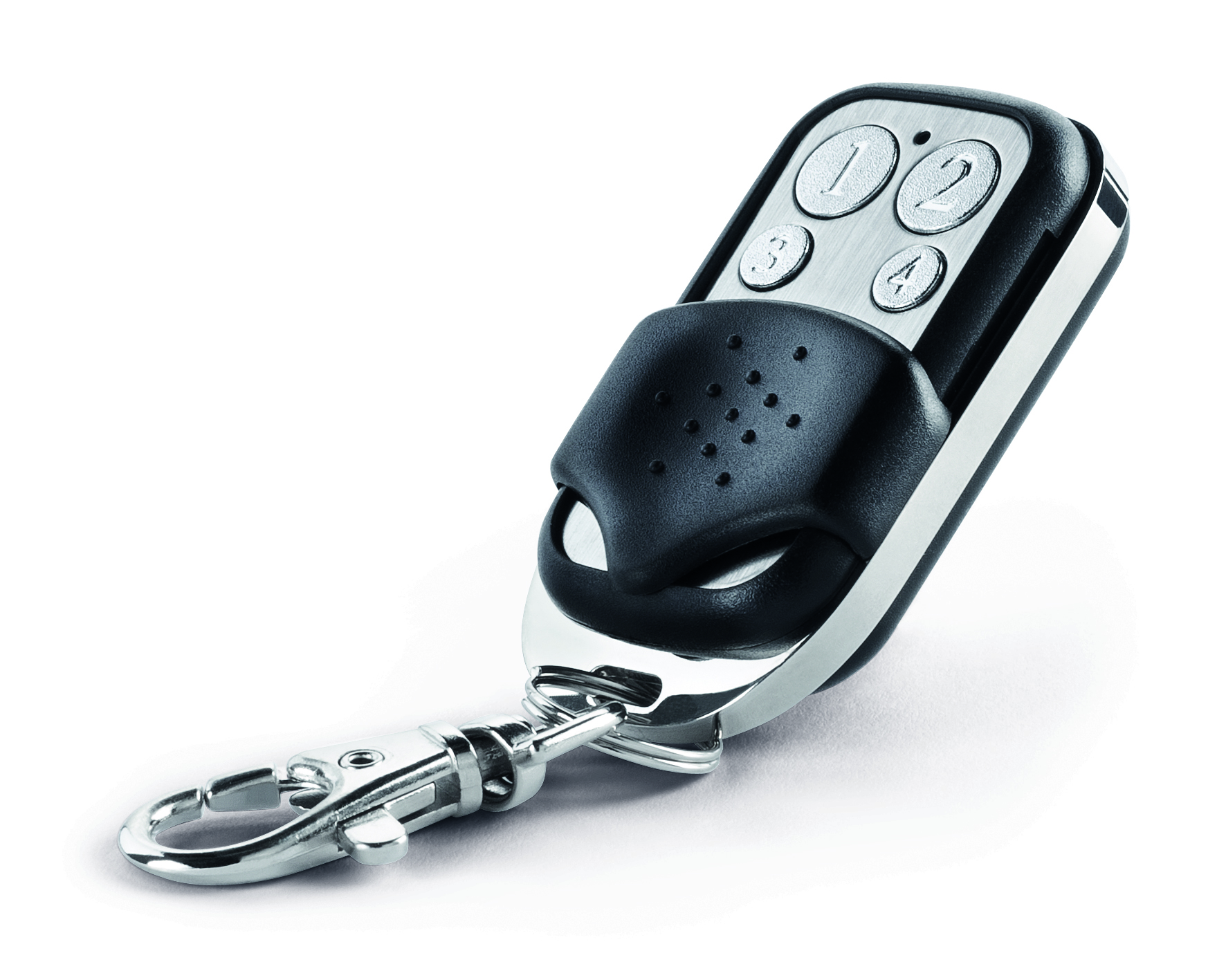
Home Control Key-Fob
SKU: DEVE9360


Quickstart
This is a
This wireless Z–Wave wall controller can act in two different modes that are activated with the first configuration action after factory default: After the first action you can further manage and configure the wall controller using the management mode. To activate this management mode push all four buttons for one second simultaneously (green blinks slowly). The buttons will have different functions then (see Installation Guidelines).
Attention:For convenience reasons some special short cut apply IF and only IF the KFOB is the primary controller of the network: The first device included into a button group will define the commands sent out by this group regardless of the default value of the configuration parameters 11-14. If the device is a door lock the button group will turn into door lock control (value=7). For dimmers and motor controls the value changes into Multilevel Switch Control (value=1). All other devices will turn the button group into Basic control (value=2). All configuration values can be changed if needed. When KFOB is primary controller the very first device included will be automatically put into button group A and the command set will change according to the rules just mentioned. All other devices need ot be put in button groups manually.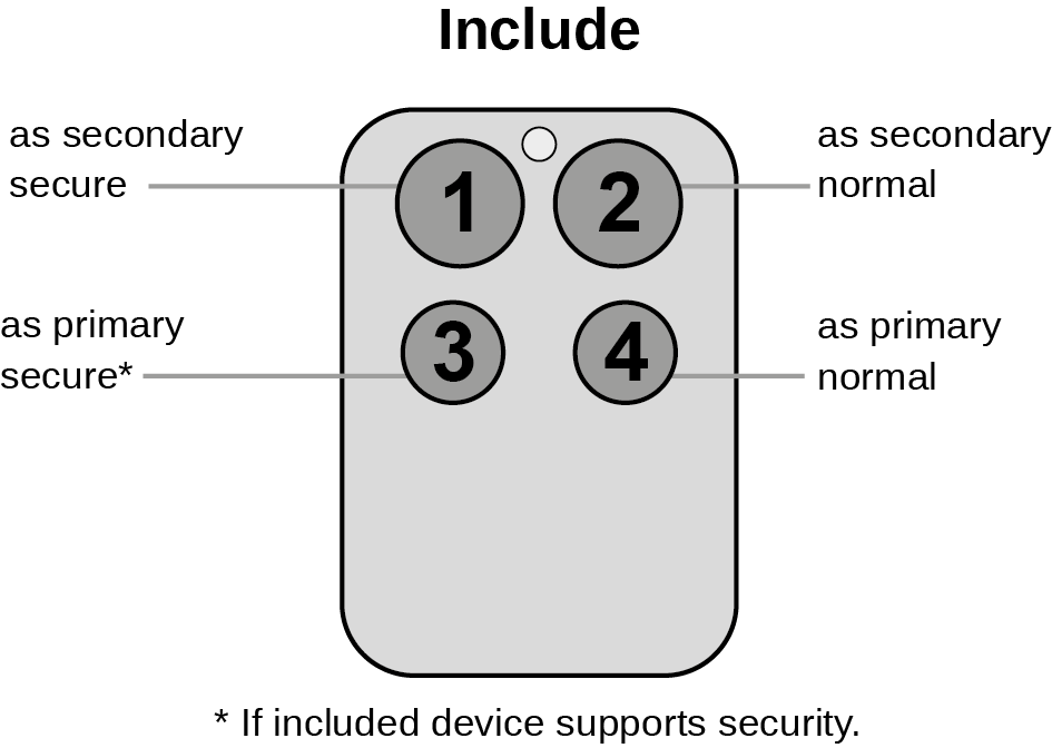
Important safety information
Please read this manual carefully. Failure to follow the recommendations in this manual may be dangerous or may violate the law. The manufacturer, importer, distributor and seller shall not be liable for any loss or damage resulting from failure to comply with the instructions in this manual or any other material. Use this equipment only for its intended purpose. Follow the disposal instructions. Do not dispose of electronic equipment or batteries in a fire or near open heat sources.Product Description
The smart home controller for your pocket. Four freely programmable function keys. Activate any Home Control components or scenarios with the push of a button. As compact as a small car key. Control your smart home from up to 100 metres (328 ft.) away.
Installation
The device comes ready to use with a battery already installed.
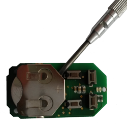
For battery change the device needs to be opened by removing the three little screws on the backside of the device. Use a screwdriver or any other usable device to gently push out the battery as shown on the picture. During reassembly watch the position of the white rubber and make sure the silver buttons fit exactly into the nipples of the rubber.
The device can be operated in two different modes: the operation mode and the management mode:
- Operation Mode: This is the mode where the device is controlling other devices.
- Management Mode: The device is turned into the management mode by pushing all four buttons for one second. A blinking LED indicates the management mode. In the management mode buttons of the device have different functions. If no further action is performed the device will turn back to the normal mode after 10 sec. Any management action terminates the management mode as well.
In management mode the following actions can be performed:
- Button 1 - Inclusion/Exclusion: Every inclusion or exclusion attempt is confirmed by hitting this button. Single Click is used for standard inclusion and exclusion, double click is used for network wide inclusion. With this operation the device can be included into a Z-Wave Network from any physical location in the network. This requires a primary controller supporting network wide inclusion. This mode lasts for 20 seconds and stops automatically. Any button press stops the mode as well.
- Button 2 - Sends Node Information Frame and Wake up Notification. (see explanation below)
- Button 3 - Activates the primary controller management menu. The following sub menu items are available:
- Button 3 followed by short click of button 1: Start Secure Inclusion
- Button 3 followed by short click of button 2: Start Unsecure Inclusion
- Button 3 followed by short click of button 3: Start Exclusion
- Button 3 followed by short click of button 4: Start Primary Handover
- Button 3 followed by pushing button 4 for 5 seconds: Factory Default Reset. After clicking on button 3 keep button 4 pushed for 4 seconds
- Button 4 - Enters into Association mode to assign target devices to one of the four associations. Refer to the manuals section about association for more information how to set and unset association groups.
In factory default mode pushing one of the four buttons for 1 sec will start different inclusion modes:
- Button 1: Include KFOB as secondary controller
- Button 2: Include KFOB as secondary controller - non secure
- Button 3: Include new device into KFOBS network
- Button 4: Include new device into KFOBS network - non secure
The process for button 1 and 2 is indicated with fast red/green blinking, the process for button 3 and 4 shows a fast green blinking. Every button push stops the process. This fast inclusion only works when device is in factory default.
Attention: For convenience reasons some special short cut apply IF and only IF the KFOB is the primary controller of the network: The first device included into a button group will define the commands sent out by this group regardless of the default value of the configuration parameters 11-14. If the device is a door lock the button group will turn into door lock control (value=7). For dimmers and motor controls the value changes into Multilevel Switch Control (value=1). All other devices will turn the button group into Basic control (value=2). All configuration values can be changed if needed. When KFOB is primary controller the very first device included will be automatically put into button group A and the command set will change according to the rules just mentioned. All other devices need ot be put in button groups manually.
Product Usage
Depending on the button mode and operating modes configured using the configuration parameters the key fob can be used in different ways.
Button modes:
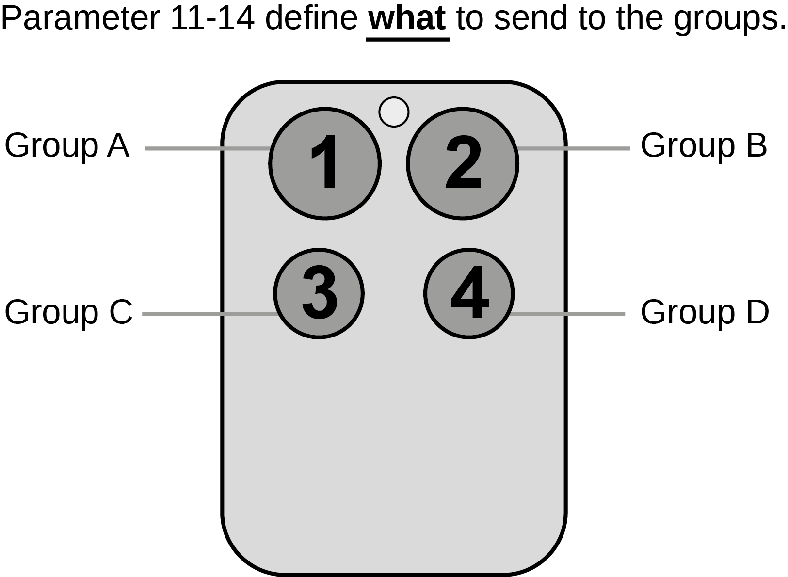
4 Groups are controlled with single button (parameter 1/2 = 0) The four buttons 1-4 control one single control group each: 1->A, 2->B, 3->C, 4->D. Single click turns devices in the control group on, double click turns them off. Click and hold can be used for dimming.
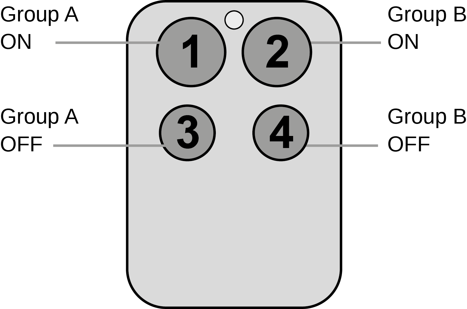
2 Groups are controlled with two buttons (parameter 1/2 = 1) The buttons 1 and 3 control the control group A (button one turns on, button three turns off), the buttons 2 and 4 control the control group B (button two turns on, button four turns off). In case dimmers are controlled, holding down the larger button will dim up, holding down the smaller button will dim down the load. Releasing the button will stop the dimming function.
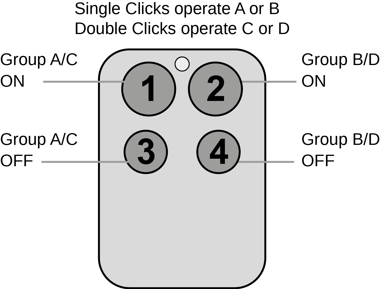
4 Groups are controlled with two buttons and double click (parameter 1/2 = 2) This mode enhances the previous mode and allows to control two further control groups C and D using double clicks.
Operating modes:
The devices supports 8 different operating modes - this means the kind of command sent out when pushing a button. Operating modes either directly control other devices or they issue various scene activation commands to a central controller. Operating modes for direct device control are:- Direct Control of associated devices with On/Off/Dim commands (parameter 11...14 = 1). Devices are controlled using Basic Set On/Off commands and Switch-Multilevel Dim Start/Stop. This mode implements communication pattern 7.
- Direct Control of associated devices with only On/Off commands (parameter 11...14 = 2). Devices are controlled using only Basic Set On/Off commands. On dimming Up event On is sent, on dimming Down Off is sent. This mode also implements communication pattern 7.
- Switch All commands (parameter 11...14 = 3) In this mode a all neighboring devices will receive Switch-All Set On/Off command and interpret it according to their membership in Switch-All groups. This mode implements communication pattern 7.
- Direct Control of Devices in proximity (parameter 11...14 = 6). Basic Set and Switch-Multilevel Dim commands are sent to a device in proximity (50...100 cm) from the Fob. Attention: In case there are more than one Z-Wave devices nearby all these devices may be switched. For this reason the proximity function should be handled with care. This mode implements communication pattern 7
- Door Lock Control (parameter 11...14 = 7) This mode allows direct control (open/close) of electronic door locks using secure communication. The mode implements communication pattern 7.
- Direct Activation of preconfigured scenes (parameter 11...14 = 5) Associated devices in an association group are controlled by individual commands defines by Z-Wave command class ?Scene Controller Configuration?. This mode enhances mode Direct Control of associated devices with On/Off/Dim commands and implements communication patterns 6 and 7. Please turn the button mode to "separate" to allow different a scene ID on every button.
- Scene Activation in IP Gateway (parameter 11...14 = 4) If configured correctly the buttons can trigger a scene in a gateway. The scene number triggered is a combination of the group number and the action performed on the button and has always two digits. The group number defines the upper digit of the scene number, the action the lower digit. The following actions are possible:
- 1 = On
- 2 = Off
- 3 = Dim Up Start
- 4 = Dim Down Start
- 5 = Dim Up Stop
- 6 = Dim Down Stop
Example: Clicking/double clicking the button will issue scene triggers, scene 11 (button 1 click, event on), scene 12 (button double click 1, event off, single button control is used in this example)
- Activation of Central Scenes (parameter 11...14 = 8,Default) Z-Wave Plus introduces a new process for scene activation - the central scene control. Pushing a button and releasing a button send a certain command to the central controller using the lifeline association group. This allows reacting both on button push and button release. This mode implements communication patterns 6 but requires a central gateway supporting Z-Wave Plus.
- Confirmation - green 1 sec
- Failure - red 1 sec
- Button press confirmation - green 1/4 sec
- Waiting for Network Management mode selection - slow green blinks
- Waiting for group selection in Association Set Mode - green fast blink
- Waiting for primary controller function selection - green fast blink
- Waiting for NIF in Association Set Mode - green-red-off blink
| Reset to factory default | Enter management mode by push all four buttons together for one second - green led blinks slowly), then hit button 3 followed by keeping button 4 pushed down for 10 seconds. The first five seconds the green LED still blinks followed by a long red, shot green sequence. Once LEDs go off, reset was executed. Please use this procedure only if the device is secondary controller and the primary controller is missing or otherwise inoperable. |
| Inclusion | 1. Start the management mode (all buttons for 5 seconds) ( green LED is blinking) 2. Press key 1 short |
| Exclusion | 1. Start the management mode (all buttons for 5 seconds) ( green LED is blinking) 2. Press key 1 short |
| NIF | Pressing Button 2 in management mode will issue a Node Information Frame. |
| Wakeup | The device will stay awake right after inclusion for 10 seconds allowing the controller to perform certain configuration. It is possible to manually wake up the device by pushing button 2 in management mode. The minimum allowed wakeup time is 240s but it?s strongly recommended to define a much longer interval since the only purpose of a wakeup should be the reporting of the battery status or an update of the child protection settings. The device has a periodic wakeup function however this function is disabled by the configuration parameter #25. This will protect the battery in case the controller is accidently configuring a wakeup interval. A wakeup of the fob outside the range of the controller will lead to lots of unsuccessful communication attempts draining the battery. Defining Node ID of 0 as a destination of the Wake up Notification will disable the periodical wakeup function as well. |
| Protection | XXXProtection |
| FirmwareUpdate | XXXFirmwareUpdate |
| SetAssociation | To control a Z-Wave device from the Key Fob the node ID of this device needs to be assigned to one of the four association groups. This is a three-step process:
|
Association Groups:
| Group Number | Maximum Nodes | Description |
|---|---|---|
| 1 | 10 | Z-Wave Plus Lifeline |
| 2 | 10 | Control Group A, controlled by button 1 or single clicks of buttons 1 and 3 |
| 3 | 10 | Control Group B, controlled by button 2 or single clicks of buttons 2 and 4 |
| 4 | 10 | Control Group C, controlled by button 3 or double clicks of buttons 1 and 3 |
| 5 | 10 | Control Group D, controlled by button 4 or double clicks of buttons 2 and 4 |
Special Operations as Z-Wave Controller
As long as this device is not included into a Z-Wave network of a different controller it is able to manage its own Z-Wave network as primary controller. As a primary controller the device can include and exclude other devices in its own network, manage associations, and reorganize the network in case of problems. The following controller functions are supported:
Inclusion of other devices
Communication between two Z-Wave devices only works if both belong to the same wireless network. Joining a network is called inclusion and is initiated by a controller. The controller needs to be turned into the inclusion mode. Once in this inclusion mode the other device needs to confirm the inclusion - typically by pressing a button.
If current primary controller in your network is in special SIS mode this and any other secondary controller can also include and exclude devices.
To become primary a contoller have to be resetted and then include a device.
For Inclusion of Z-Wave devices into the own network the following two options exist:
- In factory-default state only: Hit Button 3 (secure) or button 4 (normal) to turn the controller into inclusion state. Consult the manual of the new device how to start the inclusion process.
- Always: Turn into management mode by pressing all 4 buttons for 5 seconds. The green LED will start blinking slowly. Now hit button 3 to activate the primary controller functions. The green LED will blink faster. Now Hit Button 1 (secure) or button 2 (normal) to turn the controller into inclusion state. Consult the manual of the new device how to start the inclusion process.
Exclusion of other devices
The primary controller can exclude devices from the Z-Wave network. During exclusion the relationship between the device and the network of this controller is terminated. No communication between the device and other devices still in the network can happen after a successful exclusion. The controller needs to be turned into the exclusion mode. Once in this exclusion mode the other device needs to confirm the exclusion - typically by pressing a button.
Attention: Removing a device from the network means that it is turned back into factory default status. This process can also exclude devices from it's previous network.
Turn into management mode by pressing all 4 buttons for 5 seconds. The green LED will start blinking slowly. Now hit button 3 to activate the primary controller functions. The green LED will blink faster. Now Hit Button 3 again to turn the controller into exclusion state. Consult the manual of the new device how to start the exclusion process.
Shift of Primary Controller Role
The device can hand over its primary role to another controller and become secondary controller.
Turn into management mode by pressing all 4 buttons for 5 seconds. The green LED will start blinking slowly. Now hit button 3 to activate the primary controller functions. The green LED will blink faster. Now Hit Button 4 to turn the controller into primary shift mode. Consult the manual of the new device how to start the primary shift process for the new primary controller.
Configuration Parameters
Parameter 1: Button 1 and 3 pair mode
In separate mode button 1 works with Group A, button 3 with Group C. Click is ON, Hold is dimming UP, Double click is OFF, Click-Hold is dimming DOWN. In pair button 1/3 are UP/DOWN correspondingly. Click is ON/OFF, Hold is dimming UP/DOWN. Single clicks works with Group A, double click with Group C. Size: 1 Byte, Default Value: 1
| Setting | Description |
|---|---|
| 0 | Separately |
| 1 | In pair without double clicks |
| 2 | In pair with double clicks |
Parameter 2: Button 2 and 4 pair mode
In separate mode button 2 works with control group B, button 4 with control group D. Click is ON, Hold is dimming UP, Double click is OFF, Click-Hold is dimming DOWN. In pair button B/D are UP/DOWN correspondingly. Click is ON/OFF, Hold is dimming UP/DOWN. Single clicks works with Group B, double click with Group D. Size: 1 Byte, Default Value: 1
| Setting | Description |
|---|---|
| 0 | Separately |
| 1 | In pair without double clicks |
| 2 | In pair with double clicks |
Parameter 11: Command to control Group A
This parameter defines the command to be sent to devices of control group A when the related button is pressed. Size: 1 Byte, Default Value: 8
| Setting | Description |
|---|---|
| 0 | Disable |
| 1 | Switch on/off and Dim (send Basic Set and Switch Multilevel) |
| 2 | Switch on/off only (send Basic Set) |
| 3 | Switch all |
| 4 | Send scenes |
| 5 | Send preconfigured scenes |
| 6 | Control devices in proximity |
| 7 | Control door lock |
| 8 | Central scene to gateway (default) |
Parameter 12: Command to control Group B
This parameter defines the command to be sent to devices of control group B when the related button is pressed. Size: 1 Byte, Default Value: 8
| Setting | Description |
|---|---|
| 0 | Disable |
| 1 | Switch on/off and Dim (send Basic Set and Switch Multilevel) |
| 2 | Switch on/off only (send Basic Set) |
| 3 | Switch all |
| 4 | Send scenes |
| 5 | Send preconfigured scenes |
| 6 | Control devices in proximity |
| 7 | Control door lock |
| 8 | Central scene to gateway (default) |
Parameter 13: Command to control Group C
This parameter defines the command to be sent to devices of control group C when the related button is pressed. Size: 1 Byte, Default Value: 8
| Setting | Description |
|---|---|
| 0 | Disable |
| 1 | Switch on/off and Dim (send Basic Set and Switch Multilevel) |
| 2 | Switch on/off only (send Basic Set) |
| 3 | Switch all |
| 4 | Send scenes |
| 5 | Send preconfigured scenes |
| 6 | Send preconfigured scenes |
| 7 | Control door lock |
| 8 | Central scene to gateway |
Parameter 14: Command to control Group D
This parameter defines the command to be sent to devices of control group D when the related button is pressed. Size: 1 Byte, Default Value: 8
| Setting | Description |
|---|---|
| 0 | Disable |
| 1 | Switch on/off and Dim (send Basic Set and Switch Multilevel) |
| 2 | Switch on/off only (send Basic Set) |
| 3 | Switch all |
| 4 | Send scenes |
| 5 | Send preconfigured scenes |
| 6 | Control devices in proximity |
| 7 | Control door lock |
| 8 | Central scene to gateway (default) |
Parameter 21: Send the following switch all commands
Size: 1 Byte, Default Value: 1
| Setting | Description |
|---|---|
| 1 | Switch off only |
| 2 | Switch on only |
| 255 | Switch all on and off |
Parameter 22: Invert buttons
Size: 1 Byte, Default Value: 0
| Setting | Description |
|---|---|
| 0 | No |
| 1 | Yes |
Parameter 25: Blocks wake up even when Wake Up Interval is set
If the KFOB wakes up and there is no controller nearby, several unsuccessful communication attempts will drain battery. Size: 1 Byte, Default Value: 0
| Setting | Description |
|---|---|
| 0 | Wake up is blocked |
| 1 | Wake up is possible if configured accordingly |
Parameter 30: Send unsolicited battery report on Wake Up
Size: 1 Byte, Default Value: 1
| Setting | Description |
|---|---|
| 0 | No |
| 1 | To same node as Wake Up Notification |
| 2 | Broadcast to neighbors |
Technical Data
| Dimensions | 0.0300000x0.0550000x0.0190000 mm |
| Weight | 37 gr |
| Hardware Platform | ZM5202 |
| EAN | 4250059693609 |
| IP Class | IP 20 |
| Battery Type | 1 * CR2032 |
| Device Type | Remote Control - Simple |
| Network Operation | Portable Controller |
| Z-Wave Version | 6.51.03 |
| Certification ID | ZC10-17015376 |
| Z-Wave Product Id | 0x0175.0x0001.0x0301 |
| Frequency | Europe - 868,4 Mhz |
| Maximum transmission power | 5 mW |