Everspring
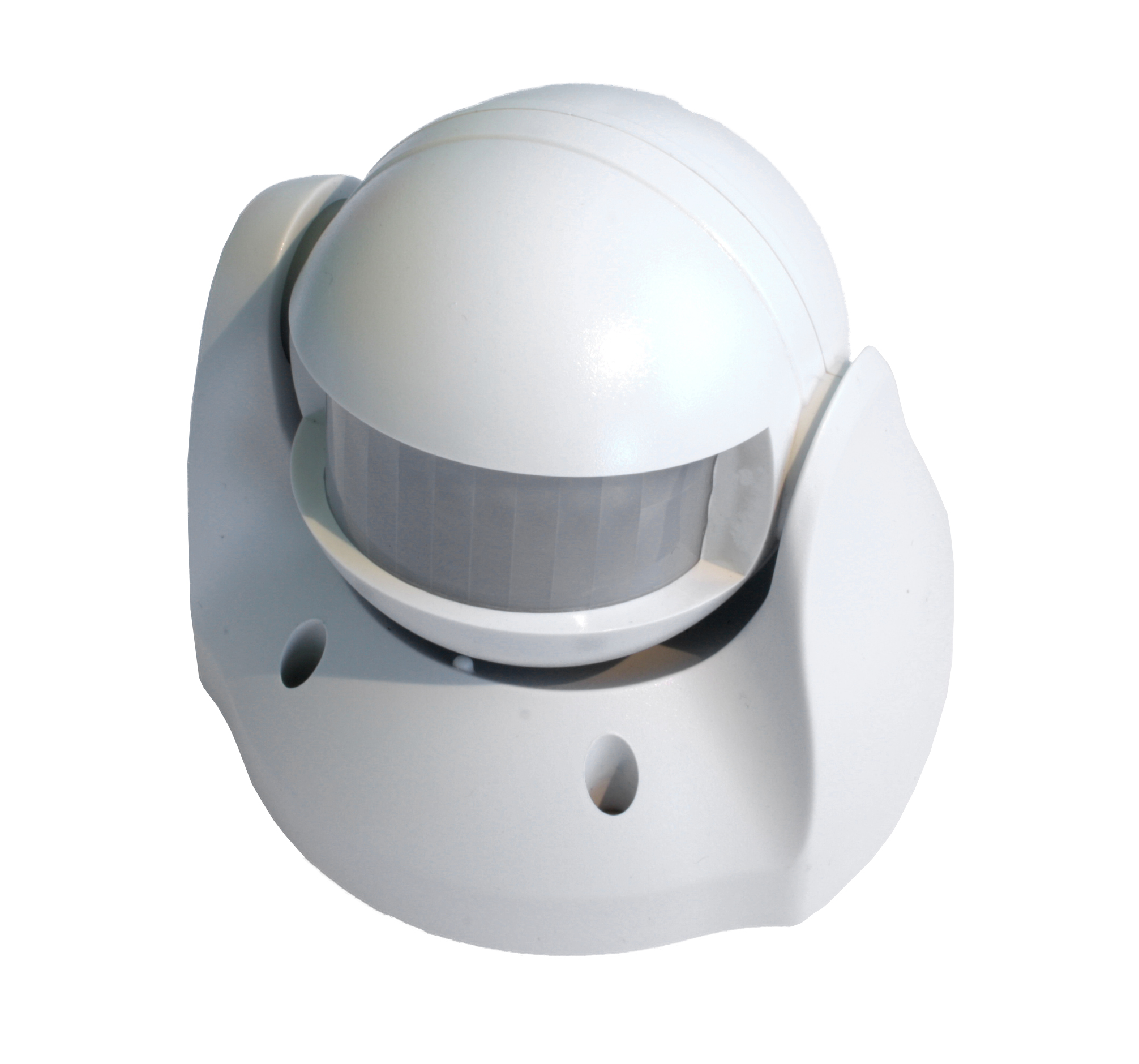
OUTDOOR MOTION DETECTOR
SKU: EVRESP816


Quickstart
This is a
Press the tamper switch 3 times within 1.5 seconds to put the unit into inclusion mode.
Important safety information
Please read this manual carefully. Failure to follow the recommendations in this manual may be dangerous or may violate the law. The manufacturer, importer, distributor and seller shall not be liable for any loss or damage resulting from failure to comply with the instructions in this manual or any other material. Use this equipment only for its intended purpose. Follow the disposal instructions. Do not dispose of electronic equipment or batteries in a fire or near open heat sources.Product Description
The SP816 Outdoor Motion Detector is a Z-Wave Plus enabled device and is fully compatible with any Z-WaveTM enabled network. The device can be set up in a Z-wave network to communicate directly with other end devices such as lighting controllers, or to report directly to a Z-wave controller (usually a gateway).
This motion detector is primarily designed for outdoor lighting control application. It features a PIR motion detector to detect movement in a protected area and a lux sensor for determining brightness of its surroundings. It comes with a built in timer to set the duration for light turn on. The lux level and the timer can be set through knobs on the device itself.
If the PIR detects motion when lux level falls below a preset setting, the device will transmit a signal to turn on the outdoor lighting (or indirectly through gateway) and then later turns it off when its timer has elapsed.
This device can also be used as a basic motion sensor for indoor security
application.
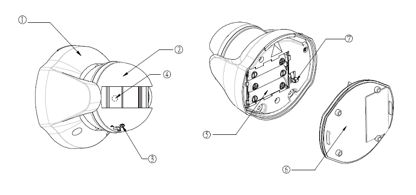
6 Rear Cover
7 Tamper Switch
1 Front Cover
2 Motion Sensor
3 Time-off / Lux Knob
4 LED indicator (hidden behind lens)
5 Battery6 Rear Cover
7 Tamper Switch
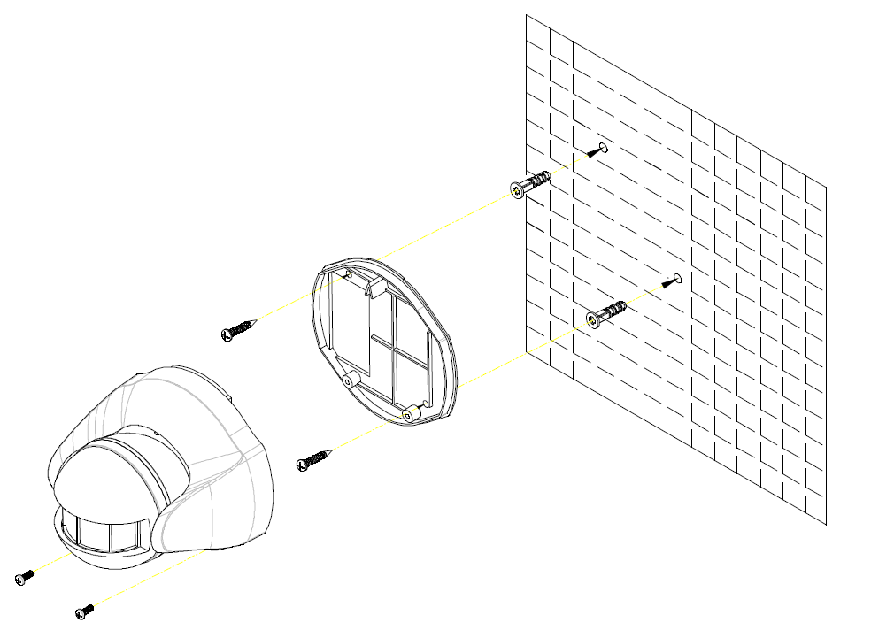
Installation
Installation
1. Use the rear cover to mark the two mounting holes.
2. Drill the holes, insert the plastic wall plugs and screw the rear cover to the wall using the screws supplied.
3. Assemble the detector back to its rear cover using screws as originally supplied.
4. The detector will enter Normal mode after 10 seconds.
Product Usage
Warm-Up
It will take approximately 1 minute for the detector to warm up after a battery is inserted. During this period the LED behind the lens will turn on. When the LED turns off, it implies warm-up procedure is complete and the detector is ready for detection.
Note:
- This will not affect the Inclusion/Exclusion process.
- After removing batteries, wait for 5 seconds to refit batteries.
Quick Test
1. With the tamper switch not being pressed, the unit will enters Test mode to allow the user to test the device before it is mounted on the wall.
2. During Test mode, if movement is detected, the LED on the detector will illuminate implying the unit is working properly.
2. During Test mode, if movement is detected, the LED on the detector will illuminate implying the unit is working properly.
3. To exit the Test mode, simply press the Tamper switch for more than 10 seconds to enter Normal mode.
Mounting the Detector
Choosing the location
The recommended location for the detector is outside the house under the eaves or other shaded areas where it is not directly exposed to sunlight. Though the detector is waterproof (IP44 rated), avoid direct contact with rain.
- Do not position the detector facing a window or direct sunlight.
- Do not position the detector directly above or facing any source of heat, eg: fires, radiators, boiler etc.
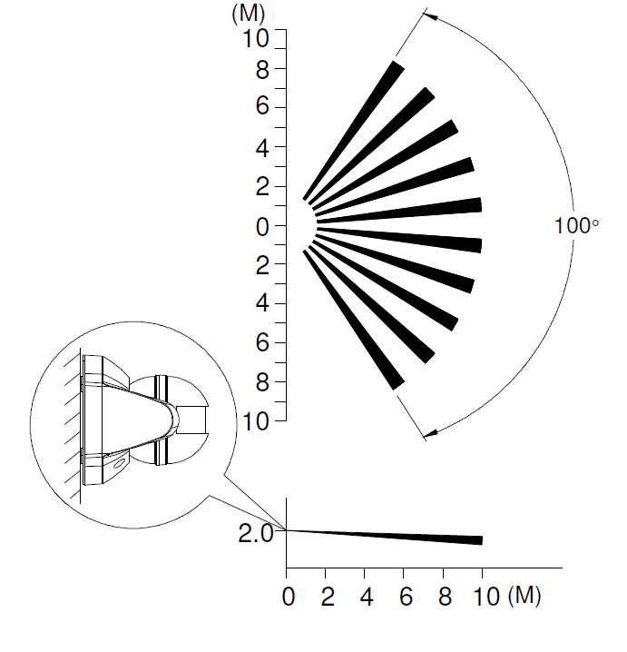
- Where possible, mount the detector so that the path of an intruder would cut across the fan pattern rather than directly towards the detector.
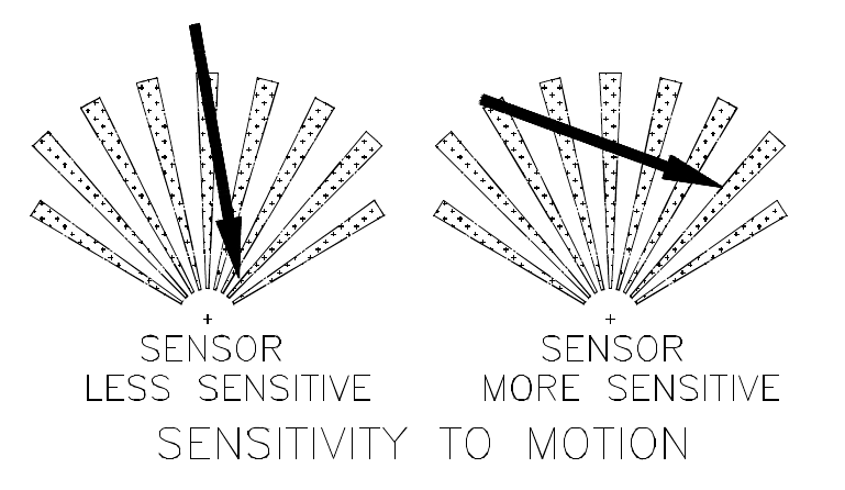
Mount the detector 2m from the floor. At this height, the detector will detect movement within its 100 degrees fan-shaped detection pattern up to 6-12m depending on adjustment.
When the detector is mounted on the wall, i.e. tamper switch is pressed, for more than 10 seconds, it will enter Normal mode.

Walk Test
The user can perform a walk test to ensure the detector’s detection range falls within the desired area of coverage. This test also checks if the detector is still within the communication range of the controller. For this test, the detector needs to be configured to turn on a connected lighting or other observable action set using the controller.
1. On the detector, turn both knobs Time-Off and Lux to the “T” mark.
2. Walk into the detector’s range and check if the connected lighting turns on and off.
3. If necessary, tilt the head of the detector to achieve desired result.
Operation
When the detector is mounted on the wall, i.e. tamper switch is pressed, for more than 10 seconds, it will enter Normal mode.
- Upon motion being sensed, the detector will turn ON the connected lighting. After the elapse of preset time-off, the detector will turn OFF the connected lighting (see Time adjustment knob below).
- In Normal mode, the red indicator LED on the detector will not illuminate when the detector is triggered in order to conserve battery life, unless the battery is low.
- If the Tamper switch is released, the detector will send a Notification command
(1) Time adjustment
(1) Time adjustment
Time-off knob controls how long the connected lighting will stay on after the motion is detected. It can be set from 5 seconds to 12 minutes.

(2) Lux adjustment
(2) Lux adjustment
The LUX adjustment sets the brightness level threshold that will activate the motion sensor in the detector.
For instance, turning the LUX knob clockwise to the MOON position will activate detector’s motion sensor only night and inactivated during the day. The adjustable Lux range is about 30 - 200 Lux.
To set the lux level:
1. Turn the Time-off knob to “T” for maximum response.
2. Turn the LUX control knob to the edge clockwise at the “moon” (dusk) position.
3. Wait until the ambient light level reaches the level of darkness at which you wish the detector to activate.
4. Slowly rotate the Lux knob while anti-clockwise while keep creating motion during the process until the detector sends out a signal to turn on the connected lighting. At this position the light should become operative at approximately the same level of darkness each evening
5. Set the Time-off knob back to the desired preset time.
Maintenance
Low Battery: When the battery becomes low, the LED will flash for 1 second when motion is detected in Normal mode to indicate low battery condition to the user. When the battery becomes low in Test mode, the LED will flash once every 30 seconds.
| Reset to factory default | 1. Press the tamper switch 3 times within 1.5 seconds to put the unit into exclusion mode. 2. Within 1 second of step 1, press the tamper switch again and hold until LED is off (about 5 seconds).
3. Node ID is excluded. The device reverts to factory default state and will be in auto-inclusion mode for 4 minutes.
|
| Inclusion | Press the tamper switch 3 times within 1.5 seconds to put the unit into inclusion mode. |
| Exclusion | Press the tamper switch 3 times within 1.5 seconds to put the unit into exclusion mode. |
| NIF | XXXNIF |
| Wakeup | XXXWakeupDescription |
| Protection | XXXProtection |
| FirmwareUpdate | XXXFirmwareUpdate |
| SetAssociation | XXXSetAssociation |
Association Groups:
| Group Number | Maximum Nodes | Description |
|---|---|---|
| 1 | 1 | Lifeline |
| 2 | 4 | PIR Control - Basic Set |
Technical Data
| Dimensions | 0.0990000x0.0940000x0.0950000 mm |
| Weight | 243 gr |
| Hardware Platform | ZM5202 |
| EAN | 4713616113359 |
| IP Class | IP 44 |
| Battery Type | 3 * AA 1,5V |
| Device Type | Motion Sensor |
| Firmware Version | 01.01 |
| Z-Wave Version | 04.3d |
| Certification ID | ZC08-13080009 |
| Z-Wave Product Id | 0x0060.0x0001.0x0005 |
| Frequency | Europe - 868,4 Mhz |
| Maximum transmission power | 5 mW |