Everspring
Z-Wave Presence Detector
SKU: EVR_SP814

Quickstart
This is a
Inclusion, Exclusion and wakeup are confirmed by three times quickly hitting the tamper switch on the backside of the case.
Important safety information
Please read this manual carefully. Failure to follow the recommendations in this manual may be dangerous or may violate the law. The manufacturer, importer, distributor and seller shall not be liable for any loss or damage resulting from failure to comply with the instructions in this manual or any other material. Use this equipment only for its intended purpose. Follow the disposal instructions. Do not dispose of electronic equipment or batteries in a fire or near open heat sources.What is Z-Wave?
Z-Wave is the international wireless protocol for communication in the Smart Home. This device is suited for use in the region mentioned in the Quickstart section.
Z-Wave ensures a reliable communication by reconfirming every message (two-way communication) and every mains powered node can act as a repeater for other nodes (meshed network) in case the receiver is not in direct wireless range of the transmitter.
This device and every other certified Z-Wave device can be used together with any other certified Z-Wave device regardless of brand and origin as long as both are suited for the same frequency range.
If a device supports secure communication it will communicate with other devices secure as long as this device provides the same or a higher level of security. Otherwise it will automatically turn into a lower level of security to maintain backward compatibility.
For more information about Z-Wave technology, devices, white papers etc. please refer to www.z-wave.info.
Product Description
This presence detector using PIR (passive infrared receiver) detects the presence of a person in a room. The units send information to a controller or any other associated Z-Wave device. Up to 4 devices can be controlled from this device. The sensor is a battery-powered device, which is in sleeping non-operative mode unless an action is detected. After a programmable sleeping time the device wakes up and sends a status information. After this the unit goes back to sleeping modus. Batteries can be changed without unscrewing the device from the door or frame. The unit will give a visual warning on the device and sends a warning to the Z-Wave controller, when batteries need to be replaced. The unit offers a tampering control and sends an alarm message when tampered.
Prepare for Installation / Reset
Please read the user manual before installing the product.
In order to include (add) a Z-Wave device to a network it must be in factory default state. Please make sure to reset the device into factory default. You can do this by performing an Exclusion operation as described below in the manual. Every Z-Wave controller is able to perform this operation however it is recommended to use the primary controller of the previous network to make sure the very device is excluded properly from this network.
Installation
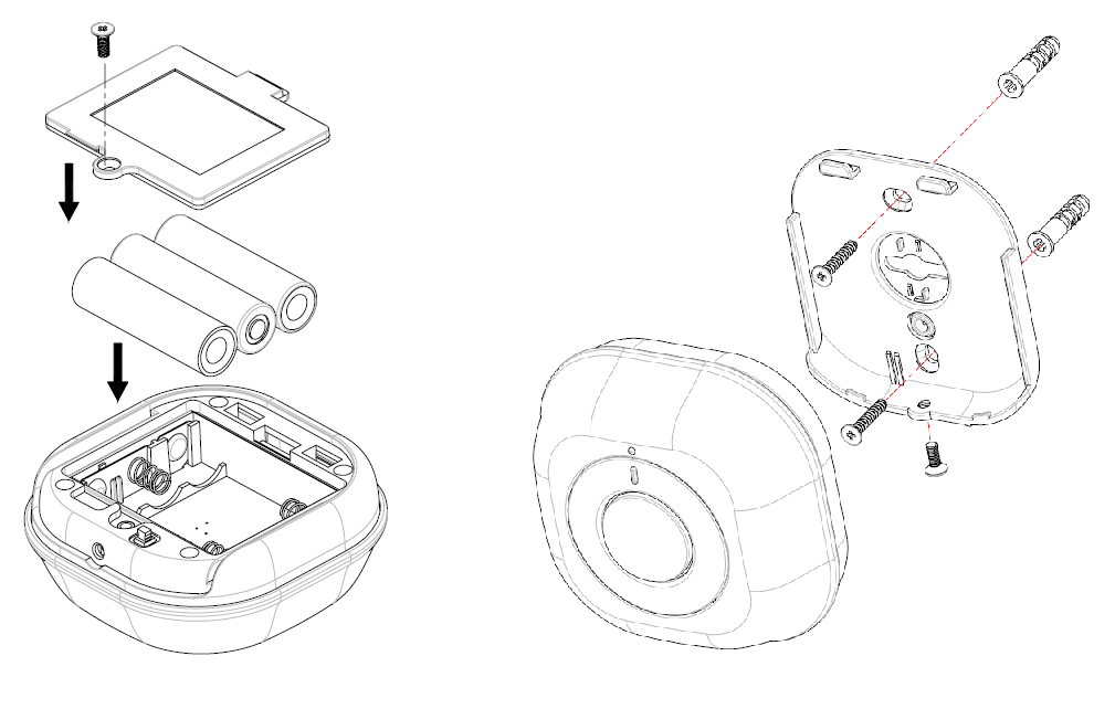
1. Release the Sensor from the battery cover by removing the fixing screws.
2. Put the 3 * AA 1.5V batteries in the battery compartment.
3. For mounting use mount plate and the screws.
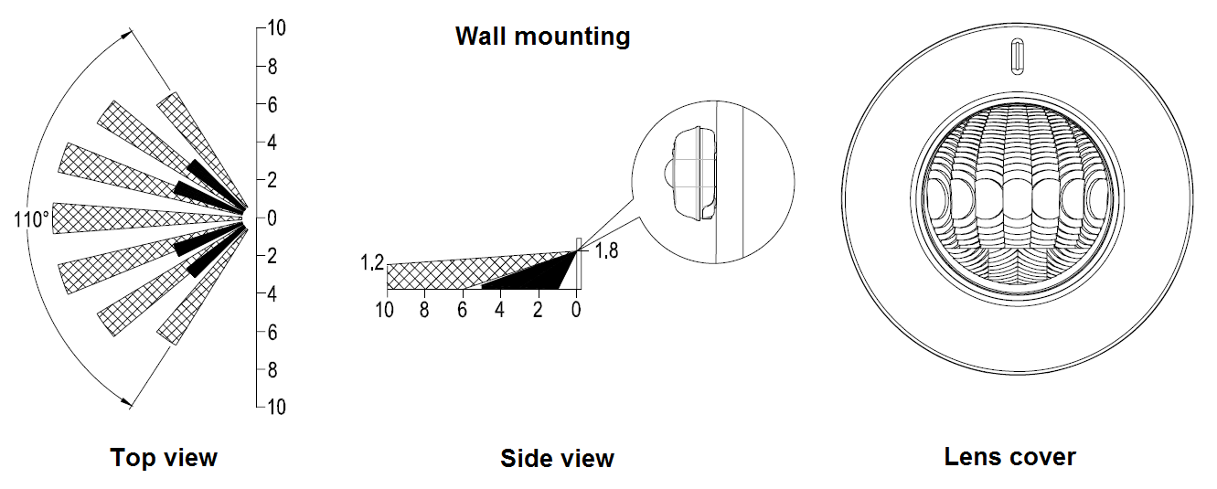
The detector can be mounted either on a wall or under a ceiling. There is a dedicated lens cover for the two mounting positions which has to be installed.
The recommended position for wall mounting is at the height of 1.8m from the floor. At this height the optimum detection range is up to 10m with coverage range of 110 degrees.
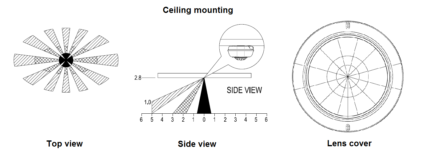
The recommended position for ceiling mounting is at the height of 2.8m from the floor. At this height, the optimum detection range is up to 5m with coverage range of 360 degrees.
Before selecting a position for a Motion Detector the following points should be noted:
Do not position the detector facing a window or direct sunlight. Motion Detectors are not suitable for use in conservatories or draughty areas.
Do not position the detector directly above or facing any source of heat, eg: fires, radiators, boiler etc.
Where possible, mount the detector so that the logical path of an intruder would cut across the fan pattern rather than directly towards the detector.
4. It will take approximately 2 minutes to warm up after battery has been connected. During this period, the detector beeps once every 3 seconds. When a long beep is sounded with red LED turns on steadily for 5 seconds, it implies warm-up procedure is completed and the detector is ready for detection.
Inclusion/Exclusion
On factory default the device does not belong to any Z-Wave network. The device needs to be added to an existing wireless network to communicate with the devices of this network. This process is called Inclusion.
Devices can also be removed from a network. This process is called Exclusion. Both processes are initiated by the primary controller of the Z-Wave network. This controller is turned into exclusion respective inclusion mode. Inclusion and Exclusion is then performed doing a special manual action right on the device.
Inclusion
Make sure that your Z-Wave Controller is in the Inclusion-/Exclusion-Mode. Click three times quickly the tamper switch behind the battery cover to confirm the process.
Exclusion
Make sure that your Z-Wave Controller is in the Inclusion-/Exclusion-Mode. Click three times quickly the tamper switch behind the battery cover to confirm the process.
Product Usage
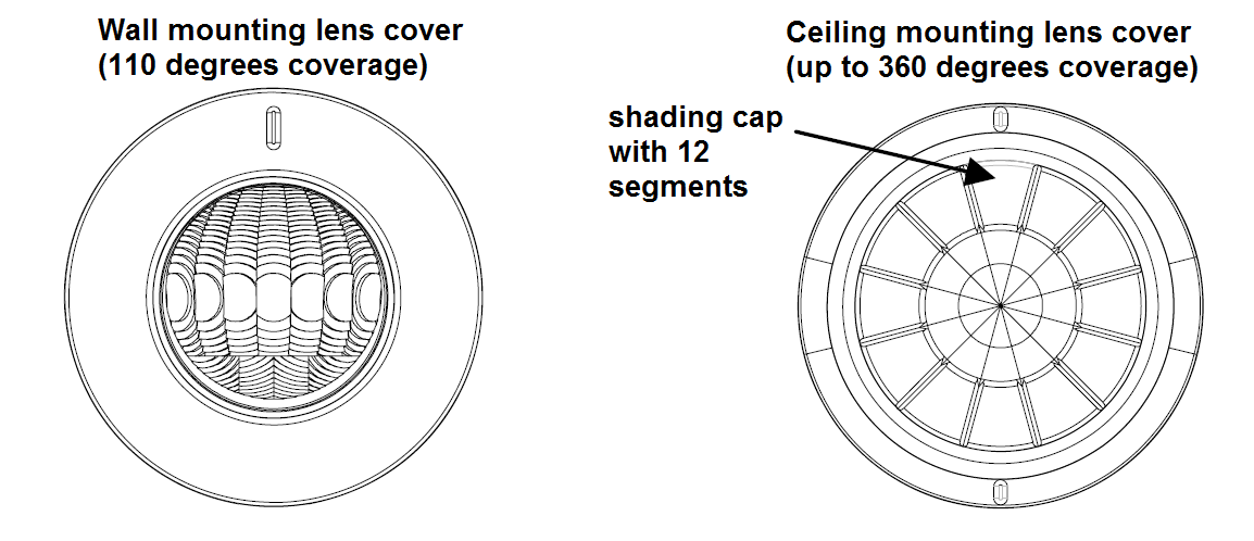
Coverage Range Adjustments:
Two types of lens covers are provided for the detector. Wall-lens cover is to be used when the detector is wall-mounted, whereas ceiling-lens cover is to be used when the detector is ceiling-mounted. The coverage range adjustment is only applicable to ceiling-lens cover; choose correct lens cover before mounting. The shading cap for ceiling mounting is composed of 12 segments for limiting the detection coverage, and each segment covers detection angle of 30 degrees. Follow the grooves on the cap, cut the cap to a suitable size and place it onto the ceiling-lens cover. The remaining segments are used for blanking off an undesirable detection area.
By walking into a protected area the detector will now be triggered each time the detector senses movement. The orange LED on the detector will be illuminated and the associated appliances will be activated. For example, siren will be sounded or indication of movement detection will be shown on the controller. It implies that the unit is working properly.
Node Information Frame
The Node Information Frame (NIF) is the business card of a Z-Wave device. It contains information about the device type and the technical capabilities. The inclusion and exclusion of the device is confirmed by sending out a Node Information Frame. Beside this it may be needed for certain network operations to send out a Node Information Frame. To issue a NIF execute the following action:
Click three times quickly on the tamper switch behind the battery cover or a detected action by the sensor sends a Node Information Frame.
Communication to a Sleeping device (Wakeup)
This device is battery operated and turned into deep sleep state most of the time to save battery life time. Communication with the device is limited. In order to communicate with the device, a static controller C is needed in the network. This controller will maintain a mailbox for the battery operated devices and store commands that can not be received during deep sleep state. Without such a controller, communication may become impossible and/or the battery life time is significantly decreased.
This device will wakeup regularly and announce the wakeup state by sending out a so called Wakeup Notification. The controller can then empty the mailbox. Therefore, the device needs to be configured with the desired wakeup interval and the node ID of the controller. If the device was included by a static controller this controller will usually perform all necessary configurations. The wakeup interval is a tradeoff between maximal battery life time and the desired responses of the device. To wakeup the device please perform the following action:
Click three times quickly on the tamper switch behind the battery cover or a detected action by the sensor will wake up the device and keep it awake.
Quick trouble shooting
Here are a few hints for network installation if things dont work as expected.
- Make sure a device is in factory reset state before including. In doubt exclude before include.
- If inclusion still fails, check if both devices use the same frequency.
- Remove all dead devices from associations. Otherwise you will see severe delays.
- Never use sleeping battery devices without a central controller.
- Dont poll FLIRS devices.
- Make sure to have enough mains powered device to benefit from the meshing
Association - one device controls an other device
Z-Wave devices control other Z-Wave devices. The relationship between one device controlling another device is called association. In order to control a different device, the controlling device needs to maintain a list of devices that will receive controlling commands. These lists are called association groups and they are always related to certain events (e.g. button pressed, sensor triggers, ...). In case the event happens all devices stored in the respective association group will receive the same wireless command wireless command, typically a 'Basic Set' Command.
Association Groups:
| Group Number | Maximum Nodes | Description |
|---|---|---|
| 1 | 5 | Devices controlled by open/close events |
Technical Data
| Dimensions | 0.0850000x0.0850000x0.0480000 mm |
| Weight | 172 gr |
| EAN | 4713616113243 |
| Device Type | Routing Binary Sensor |
| Generic Device Class | Binary Sensor |
| Specific Device Class | Routing Binary Sensor |
| Firmware Version | 01.03 |
| Z-Wave Version | 02.40 |
| Certification ID | ZC08-09100003 |
| Z-Wave Product Id | 0086.0002.0004 |
| Frequency | Europe - 868,4 Mhz |
| Maximum transmission power | 5 mW |
Supported Command Classes
- Basic
- Battery
- Wake Up
- Association
- Version
- Sensor Binary
- Alarm
- Manufacturer Specific
Controlled Command Classes
- Basic
- Alarm
Explanation of Z-Wave specific terms
- Controller — is a Z-Wave device with capabilities to manage the network. Controllers are typically Gateways,Remote Controls or battery operated wall controllers.
- Slave — is a Z-Wave device without capabilities to manage the network. Slaves can be sensors, actuators and even remote controls.
- Primary Controller — is the central organizer of the network. It must be a controller. There can be only one primary controller in a Z-Wave network.
- Inclusion — is the process of adding new Z-Wave devices into a network.
- Exclusion — is the process of removing Z-Wave devices from the network.
- Association — is a control relationship between a controlling device and a controlled device.
- Wakeup Notification — is a special wireless message issued by a Z-Wave device to announces that is able to communicate.
- Node Information Frame — is a special wireless message issued by a Z-Wave device to announce its capabilities and functions.