Fibaro
Smart Implant
SKU: FIBEFGBS-222


Quickstart
This is a
1.Set the main controller in Security S2 Authenticated add mode (see the controllers manual).
2.Scan the DSK QR code or input the 5-digit PIN code (label on the bottom of the box).
3.Power the device.
4.LED will start blinking yellow, wait for the adding process to end.
5.Successful adding will be confirmed by the Z-Wave controllers message.
Important safety information
Please read this manual carefully. Failure to follow the recommendations in this manual may be dangerous or may violate the law. The manufacturer, importer, distributor and seller shall not be liable for any loss or damage resulting from failure to comply with the instructions in this manual or any other material. Use this equipment only for its intended purpose. Follow the disposal instructions. Do not dispose of electronic equipment or batteries in a fire or near open heat sources.Product Description
FIBARO Smart Implant allows to enhance the functionality of wired sensors and other devices by adding Z-Wave network communication.You can connect binary sensors, analog sensors, DS18B20 temperature sensors or DHT22 humidity and temperature sensor to report their readings to the Z-Wave controller.It can also control devices by opening/closing output contacts independently of the inputs.Main features of FIBARO Smart Implant:- Compatible with any Z-Wave or Z-Wave+ Controller,- Supports Z-Wave network Security Modes: S0 with AES-128 encryption and S2 with PRNG-based encryption,- Allows for connecting sensors: o6 DS18B20 sensors,o1 DHT sensor, o2 2-wire analog sensor, o2 3-wire analog sensor, o2 binary sensors. - Works as a Z-Wave signal repeater,- Built-in temperature sensor.
Installation
- Connect only in accordance with one of the diagrams,
- The device is powered with secure voltage; nevertheless, the user should be extra careful or should commission the installation to a qualified person,
- Do not connect devices which are not compliant with the specification,
- Do not connect other sensors than DS18B20 or DHT22 to SP and SD terminals,
- Do not connect sensors to SP and SD terminals with wires longer than 3 meters,
- Do not load the device outputs with a current exceeding 150mA,
- Every connected device should be compliant with the relevant safety standards,
- Unused lines should be left insulated.
1. Turn off the alarm system.
2. Connect with one of the diagrams below:
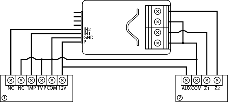
Example connection with regular alarm line (1 alarm sensor, 2 alarm system hub).
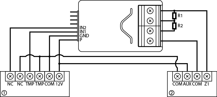
Example connection with parametric alarm line (1 alarm sensor, 2 alarm system hub).
3. Verify correctness of connection.
4. Arrange the device and its antenna in the housing.
5. Power the device.
6. Add the device to the Z-Wave network.
7. Change values of parameters:
- Connected to IN1:
- Normally close: change parameter 20 to 0
- Normally open: change parameter 20 to 1
- Connected to IN2:
- Normally close: change parameter 21 to 0
- Normally open: change parameter 21 to 1
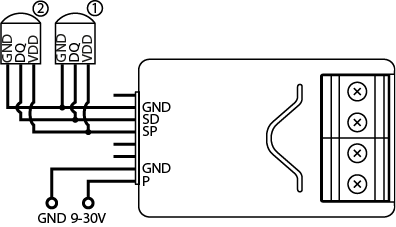
The DS18B20 sensor may easily be installed wherever very precise temperature measurements are required. If proper protective measures are undertaken, the sensor may be used in humid environments or under water, it may be embedded in concrete or placed under the floor.
You can connect up to 6 DS18B20 sensors in parallel to SP-SD terminals.
1. Disconnect Power
2. Connect with the diagram below
3. Verify correctness of connection.
4. Power the device.
5. Add the device to the Z-Wave network.
Connection with DHT22
The DHT22 sensor may easily be installed wherever humidity and temperature measurements are required.
You can connect only 1 DHT22 sensor to TP-TD terminals.
2. Connect with the diagram below
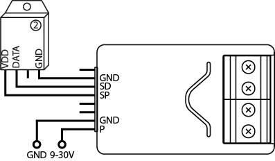
3. Verify correctness of connection.
4. Power the device.
5. Add the device to the Z-Wave network.
6. Change values of parameters:
- Connected to IN1: change parameter 20 to 4
- Connected to IN2: change parameter 21 to 4
The 2-wire analog sensor requires pull-up resistor.
You can connect up to 2 analog sensors to IN1/IN2 terminals.
The 12V supply is required for these type of sensors.
1. Disconnect Power
2. Connect with the diagram below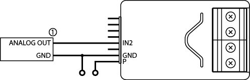
3. Verify the correctness of connection.
4. Power the device.
5. Add the device to the Z-Wave network.
6. Change values of parameters:
- Connected to IN1: change parameter 20 to 5
- Connected to IN2: change parameter 21 to 5
You can connect up to 2 analog sensors IN1/IN2 terminals.
1. Disconnect Power
2. Connect with the diagram below
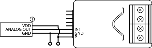
3. Verify the correctness of connection.
4. Power the device.
5. Add the device to the Z-Wave network.
6. Change values of parameters:
- Connected to IN1: change parameter 20 to 4
- Connected to IN2: change parameter 21 to 4
You connect normally opened or normally binary sensors to IN1/IN2 terminals.
1. Disconnect Power
2. Connect with the diagram below
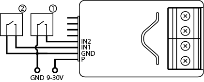
3. Verify the correctness of connection.
4. Power the device.
5. Add the device to the Z-Wave network.
6. Change values of parameters
6.1 Binary sensor
- Connected to IN1:
- Normally close: change parameter 20 to 0
- Normally open: change parameter 20 to 1
- Connected to IN2:
- Normally close: change parameter 21 to 0
- Normally open: change parameter 21 to 1
- Connected to IN1:
- Monostable: change parameter 20 to 2
- Bistable: change parameter 20 to 3
- Connected to IN2:
- Monostable: change parameter 21 to 2
- Bistable: change parameter 21 to 3
Smart Implant can be connected to different devices to control them. In this example it is connected to gate opener with impulse input (every impulse will start and stop the gate motor, alternately opening/closing).
1. Disconnect Power
2. Connect with the diagram below
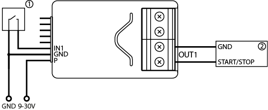
3. Verify the correctness of connection.
4. Power the device.
5. Add the device to the Z-Wave network.
6. Change values of parameters:
- Connected to IN1 and OUT1:
- Change parameter 20 to 2 (monostable button)
- Change parameter 156 to 1 (0.1s)
- Connected to IN2 and OUT2:
- Change parameter 21 to 2 (monostable button)
- Change parameter 157 to 1 (0.1s)
Product Usage
Tips for arranging the antenna:
- Locate the antenna as far from metal elements as possible (connecting wires, bracket rings, etc.) in order to prevent interferences,
- Metal surfaces in the direct vicinity of the antenna (e.g. flush mounted metal boxes, metal door frames) may impair signal reception!
- Do not cut or shorten the antenna - its length is perfectly matched to the band in which the system operates.
- Make sure no part of the antenna sticks out of the wall switch box.
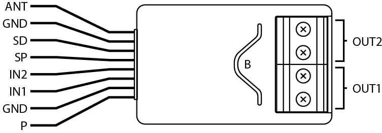
ANT (black) - antenna
GND (blue) - ground conductor
SD (white) - signal conductor for DS18B20 or DHT22 sensor
SP (brown) - power supply conductor for DS18B20 or DHT22 sensor (3.3V)
IN2 (green) - input no. 2
IN1 (yellow) - input no. 1
GND (blue) - ground conductor
P (red) - power supply conductor
OUT1 - output no. 1 assigned to input IN1
OUT2 - output no. 2 assigned to input IN2
B - service button (used to add/remove the device)
Range Tester
The device has a built in Z-Wave network main controllers range tester.
Note: To make Z-Wave range test possible, the device must be added to the Z-Wave controller. Testing may stress the network, so it is recommended to perform the test only in special cases.
To test the main controllers range:
- Press and hold the button to enter the menu.
- Release button when the device glows magenta.
- Quickly click the button to confirm.
- Visual indicator will indicate the Z-Wave networks range (range signaling modes described below).
- To exit Z-Wave range test, press the button briefly.
Z-Wave range tester signalling modes:
- Visual indicator pulsing green - the device attempts to establish a direct communication with the main controller. If a direct communication attempt fails, the device will try to establish a routed communication, through other modules, which will be signalled by visual indicator pulsing yellow.
- Visual indicator glowing green - the device communicates with the main controller directly.
- Visual indicator pulsing yellow - the device tries to establish a routed communication with the main controller through other modules (repeaters).
- Visual indicator glowing yellow - the device communicates with the main controller through the other modules. After 2 seconds the device will retry to establish a direct communication with the main controller, which will be signalled with visual indicator pulsing green.
- Visual indicator pulsing violet - the device does communicate at the maximum distance of the Z-Wave network. If connection proves successful it will be confirmed with a yellow glow. Its not recommended to use the device at the range limit.
- Visual indicator glowing red - the device is not able to connect to the main controller directly or through another Z-Wave network device (repeater).
Note: The communication mode of the device may switch between direct and one using routing, especially if the device is on the limit of the direct range.
Visual indications
The built-in LED light shows current device status.
After powering the device:
- Green - device added to a Z-Wave network (without Security S2 Authenticated)
- Magenta - device added to a Z-Wave network (with Security S2 Authenticated)
- Red - device not added to a Z-Wave network
Update:
- Blinking cyan - update in progress
- Green - update successful (added without Security S2 Authenticated)
- Magenta - update successful (added with Security S2 Authenticated)
- Red - update not successful
Menu:
- 3 green blinks - entering the menu (added without Security S2 Authenticated)
- 3 magenta blinks - entering the menu (added with Security S2 Authenticated)
- 3 red blinks - entering the menu (not added to a Z-Wave network)
- Magenta - range test
- Yellow - reset
Menu
Menu allows to perform Z-Wave network actions. In order to use the menu:
1. Press and hold the button to enter the menu, device blinks to signal adding status (see 7.1: Visual indications).
2. Release the button when device signals desired position with colour:
- MAGENTA - start range test
- YELLOW - reset the device
Activating scenes
The device can activate scenes in the Z-Wave controller by sending scene ID and attribute of a specific action using Central Scene Command Class.
In order for this functionality to work connect the monostable or bistable switch to the IN1 or IN2 input and set parameter 20 (IN1) or 21 (IN2) to 2 or 3.
By default scenes are not activated, set parameters 40 and 41 to enable scene activation for selected actions.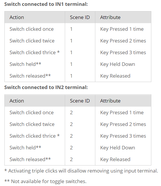
| Reset to factory default | 1.Press and hold the button to enter the menu. 2.Release button when the device glows yellow. 3.Quickly click the button to confirm. 4.After few seconds the device will be restarted, which is signalled with the red colour. |
| Inclusion | 1.Power the device. 2.Set the main controller in (Security/non-Security Mode) add mode (see the controllers manual). 3.Quickly, triple click button on the device housing or switch connected to IN1 or IN2. 4.If you are adding in Security S2 Authenticated, scan the DSK QR code or input the 5-digit PIN code (label on the bottom of the box). 5.LED will start blinking yellow, wait for the adding process to end. 6.Successful adding will be confirmed by the Z-Wave controllers message. To add the device to the Z-Wave network using |
| Exclusion | 1.Power the device. 2.Set the main controller into remove mode (see the controllers manual). 3.Quickly, triple click button on the device housing or switch connected to IN1 or IN2. 4.LED will start blinking yellow, wait for the removing process to end. 5.Successful removing will be confirmed by the Z-Wave controllers message. |
| NIF | XXXNIF |
| Wakeup | FIBARO Smart Implant is powered using DC power supply unit so it is always awake. |
| Protection | XXXProtection |
| FirmwareUpdate | XXXFirmwareUpdate |
| SetAssociation | XXXSetAssociation |
Association Groups:
| Group Number | Maximum Nodes | Description |
|---|---|---|
| 1 | 1 | Lifeline reports the device status and allows for assigning single device only (main controller by default). |
| 2 | 5 | On/Off (IN1) is assigned to IN1 input terminal (uses Basic command class). |
| 3 | 5 | On/Off (IN2) is assigned to IN2 input terminal (uses Basic command class). |
Configuration Parameters
Parameter 20: Input 1 - operating mode
This parameter allows to choose mode of 1st input (IN1). Change it depending on connected device. Size: 1 Byte, Default Value: 2
| Setting | Description |
|---|---|
| 0 | Normally closed alarm input (Notification) |
| 1 | Normally open alarm input (Notification) |
| 2 | Monostable button (Central Scene) |
| 3 | Bistable button (Central Scene) |
| 4 | Analog input without internal pull-up (Sensor Multilevel) |
| 5 | Analog input with internal pullup (Sensor Multilevel) |
Parameter 21: Input 2 - operating mode
This parameter allows to choose mode of 2nd input Size: 1 Byte, Default Value: 2
| Setting | Description |
|---|---|
| 0 | Normally closed alarm input (Notification CC) |
| 1 | Normally open alarm input (Notification CC) |
| 2 | Monostable button (Central Scene CC) |
| 3 | Bistable button (Central Scene CC) |
| 4 | Analog input without internal pull-up (Sensor Multilevel CC) |
| 5 | Analog input with internal pullup (Sensor Multilevel CC) |
Parameter 24: Inputs orientation
This parameter allows reversing operation of IN1 and IN2 inputs without changing the wiring. Use in case of incorrect wiring. Size: 1 Byte, Default Value: 0
| Setting | Description |
|---|---|
| 0 | default (IN1 - 1st input, IN2 - 2nd input) |
| 1 | reversed (IN1 - 2nd input, IN2 - 1st input) |
Parameter 25: Outputs orientation
This parameter allows reversing operation of OUT1 and OUT2 inputs without changing the wiring. Use in case of incorrect wiri ng. Size: 1 Byte, Default Value: 0
| Setting | Description |
|---|---|
| 0 | default (OUT1 - 1st output, OUT2 - 2nd output) |
| 1 | reversed (OUT1 - 2nd output, OUT2 - 1st output) |
Parameter 40: Input 1 - sent scenes
This parameter defines which actions result in sending scene ID and attribute assigned to them (see 9: Activating scenes). Parameter is relevant only if parameter 20 is set to 2 or 3. Size: 1 Byte, Default Value: 0
| Setting | Description |
|---|---|
| 1 | Key pressed 1 time |
| 2 | Key pressed 2 times |
| 4 | Key pressed 3 times |
| 8 | Key hold down and key released |
Parameter 41: Input 2 - sent scenes
This parameter defines which actions result in sending scene ID and attribute assigned to them (see 9: Activating scenes). Parameter is relevant only if parameter 20 is set to 2 or 3. Size: 1 Byte, Default Value: 0
| Setting | Description |
|---|---|
| 1 | Key pressed 1 time |
| 2 | Key pressed 2 time |
| 4 | Key pressed 3 time |
| 8 | Key hold down and key released |
Parameter 47: Input 1 - value sent to 2nd association group when activated
This parameter defines value sent to devices in 2nd associationgroup when IN1 input is triggered (using Basic Command Class). Size: 2 Byte, Default Value: 255
| Setting | Description |
|---|---|
| 0 - 255 | Value send to devices |
Parameter 49: Input 1 - value sent to 2nd association group when deactivated
This parameter defines value sent to devices in 2nd association group when IN1 input is deactivated (using Basic Command Class). Size: 2 Byte, Default Value: 0
| Setting | Description |
|---|---|
| 0 - 255 | value send to devices |
Parameter 52: Input 2 - value sent to 3rd association group when activated
This parameter defines value sent to devices in 3rd association group when IN2 input is triggered (using Basic Command Class). Size: 2 Byte, Default Value: 255
| Setting | Description |
|---|---|
| 0 - 255 | value send to devices |
Parameter 54: Input 2 - value sent to 3rd association group when deactivated
This parameter defines value sent to devices in 2nd association group when IN2 input is deactivated (using Basic Command Class). Size: 2 Byte, Default Value: 0
| Setting | Description |
|---|---|
| 0 - 255 | value send to devices |
Parameter 63: Analog inputs - minimal change to report
This parameter defines minimal change (from the last reported) of analog input value that results in sending new report. Parameter is relevant only for analog inputs (parameter 20 or 21 set to 4 or 5). Size: 1 Byte, Default Value: 5
| Setting | Description |
|---|---|
| 0 | reporting on change disabled |
| 1 - 100 | (0.1-10V, 0.1V step) |
Parameter 64: Analog inputs - periodical reports
This parameter defines reporting period of analog inputs value. Periodical reports are independent from changes in value (parameter 63). Parameter is relevant only for analog inputs (parameter 20 or 21 set to 4 or 5). Size: 2 Byte, Default Value: 0
| Setting | Description |
|---|---|
| 0 | periodical reports disabled |
| 60 - 32400 | (60s-9h) |
Parameter 65: Internal temperature sensor - minimal change to report
This parameter defines minimal change (from the last reported) of internal temperature sensor value that results in sending new report. Size: 2 Byte, Default Value: 5
| Setting | Description |
|---|---|
| 0 | reporting on change disabled |
| 1 - 255 | (0.1-25.5C) |
Parameter 66: Internal temperature sensor - periodical reports
This parameter defines reporting period of internal temperature sensor value. Periodical reports are independent from changes in value (parameter 65). Size: 2 Byte, Default Value: 0
| Setting | Description |
|---|---|
| 0 | periodical reports disabled |
| 60 - 32400 | (60s-9h) |
Parameter 67: External sensors - minimal change to report
This parameter defines minimal change (from the last reported) of external sensors values (DS18B20 or DHT22) that results in sending new report. Parameter is relevant only for connected DS18B20 or DHT22 sensors. Size: 2 Byte, Default Value: 5
| Setting | Description |
|---|---|
| 0 | reporting on change disabled |
| 1 - 255 | (0.1-25.5 units, 0.1) |
Parameter 68: External sensors - periodical reports
This parameter defines reporting period of analog inputs value. Periodical reports are independent from changes in value (parameter 67). Parameter is relevant only for connected DS18B20 or DHT22 sensors. Size: 2 Byte, Default Value: 0
| Setting | Description |
|---|---|
| 0 | periodical reports disabled |
| 60 - 32400 | (60s-9h) |
Parameter 150: Input 1 - sensitivity
This parameter defines the inertia time of IN1 input in alarm modes. Adjust this parameter to prevent bouncing or signal disruptions.Parameter is relevant only if parameter 20 is set to 0 or 1 (alarm mode). Size: 1 Byte, Default Value: 10
| Setting | Description |
|---|---|
| 1 - 100 | (10ms-1000ms, 10ms step) |
Parameter 151: Input 2 - sensitivity
This parameter defines the inertia time of IN2 input in alarm modes. Adjust this parameter to prevent bouncing or signal disruptions. Parameter is relevant only if parameter 21 is set to 0 or 1 (alarm mode). Size: 1 Byte, Default Value: 10
| Setting | Description |
|---|---|
| 1 - 100 | (10ms-1000ms, 10ms step) |
Parameter 152: Input 1 - delay of alarm cancellation
This parameter defines additional delay of cancelling the alarm on IN1 input. Parameter is relevant only if parameter 20 is set to 0 or 1 (alarm mode). Size: 2 Byte, Default Value: 0
| Setting | Description |
|---|---|
| 0 | no delay |
| 1 - 3600 | (in seconds) |
Parameter 153: Input 2 - delay of alarm cancellation
This parameter defines additional delay of cancelling the alarm on IN2 input. Parameter is relevant only if parameter 21 is set to 0 or 1 (alarm mode). Size: 2 Byte, Default Value: 0
| Setting | Description |
|---|---|
| 0 | no delay |
| 1 - 3600 | (in seconds) |
Parameter 154: Output 1 - logic of operation
This parameter defines logic of OUT1 output operation. Size: 1 Byte, Default Value: 0
| Setting | Description |
|---|---|
| 0 | contacts normally open / closed when active |
| 1 | contacts normally closed / open when active |
Parameter 155: Output 2 - logic of operation
This parameter defines logic of OUT2 output operation. Size: 1 Byte, Default Value: 0
| Setting | Description |
|---|---|
| 0 | contacts normally open / closed when active |
| 1 | contacts normally closed / open when active |
Parameter 156: Output 1 - auto off
This parameter defines time after which OUT1 will be automatically deactivated. Size: 2 Byte, Default Value: 0
| Setting | Description |
|---|---|
| 0 | auto off disabled |
| 1 - 27000 | (0.1s-45min, 0.1s step) |
Parameter 157: Output 2 - auto off
This parameter defines time after which OUT2 will be automatically deactivated. Size: 2 Byte, Default Value: 0
| Setting | Description |
|---|---|
| 0 | auto off disabled |
| 1 - 27000 | (0.1s-45min, 0.1s step) |
Technical Data
| Dimensions | 17,5 x 29 x 13 mm |
| Hardware Platform | ZM5101 |
| EAN | 5902701701475 |
| IP Class | IP 20 |
| Voltage | 9-30 V |
| Load | 150mA |
| Device Type | Notification Sensor |
| Network Operation | Always On Slave |
| Z-Wave Version | 6.81.01 |
| Certification ID | ZC10-19046414 |
| Z-Wave Product Id | 0x010F.0x0502.0x1000 |
| Color | White |
| Supported Notification Types | Home SecuritySystem |
| Sensors | Open/Closed (Binary) |
| Frequency | Europe - 868,4 Mhz |
| Maximum transmission power | 5 mW |