FIBARO
FIBARO CO Sensor
SKU: FIBEFGCD-001


Quickstart
This is a
Important safety information
Please read this manual carefully. Failure to follow the recommendations in this manual may be dangerous or may violate the law. The manufacturer, importer, distributor and seller shall not be liable for any loss or damage resulting from failure to comply with the instructions in this manual or any other material. Use this equipment only for its intended purpose. Follow the disposal instructions. Do not dispose of electronic equipment or batteries in a fire or near open heat sources.Product Description
Installation
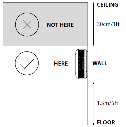
Note: Recommended height of installation is dependant on the purpose of the room and height at which head typically is.
Place of installation:
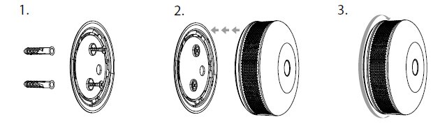
Installation on the wall:
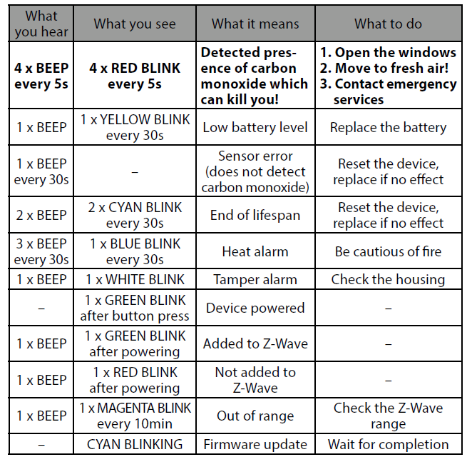
Product Usage
| Reset to factory default | 1. Press and hold the button.
2. Release the button when LED indicator glows white.
3. Click the button when LED indicator glows yellow.
4. After few seconds the device will be reset (confirmed by red LED indicator). |
| Inclusion | 1. Place the device within direct range of the Z-Wave controller.
2. Set the main Z-Wave controller in (security/non-security) adding mode (see the controller’s manual).
3. Quickly, triple click the button located on the casing.
4. Wait for the device to be added into the system.
5. Successful adding will be confirmed by the Z-Wave controller’s message |
| Exclusion | 1. Place the device within direct range of the Z-Wave controller.
2. Set the main Z-Wave controller in remove mode (see the controller’s manual).
3. Quickly, triple click the button located on the casing.
4. Wait for the removing process to end.
5. Successful removing will be confirmed by the Z-Wave controller’s message. |
| NIF | XXXNIF |
| Wakeup | Click the button. |
| Protection | XXXProtection |
| FirmwareUpdate | XXXFirmwareUpdate |
| SetAssociation | XXXSetAssociation |
Association Groups:
| Group Number | Maximum Nodes | Description |
|---|---|---|
| 1 | 1 | Lifeline - reports the device status and allows for assigning single device only (main controller by default). |
| 2 | 5 | CO Alarm - is assigned to the device status - devices in this group will be switched on/off when CO Alarm status changes. |
| 3 | 5 | CO Alarm - is assigned to the device status - devices in this group will receive notification when CO Alarm status changes. Useful for devices that can trigger alarms. |
| 4 | 5 | CO Level - is assigned to measured CO level - devices in this group will be switched on/off after exceeding the level of CO concentration specified in parameter 14. |
| 5 | 5 | Tamper Alarm - is assigned to the tamper - sends tamper alarm and cancellation frames to the associated devices. |
| 6 | 5 | CO Alarm BC - is assigned to the device status - devices in this group will be switched on/off when CO Alarm status changes. Provides backward compatibility with controllers not supporting Z-Wave+ protocol. |
| 7 | 5 | Tamper Alarm BC - is assigned to the tamper - sends tamper alarm and alarm cancellation frames to the associated devices. Provides backward compatibility with controllers not supporting Z-Wave+ protocol. |
Configuration Parameters
Parameter 2: Z-Wave notifications
This parameter allows to set the actions which result in sending notifications to the Z-Wave network controller. Size: 1 Byte, Default Value: 0
| Setting | Description |
|---|---|
| 0 | both actions disabled |
| 1 | tampering (opened casing) |
| 2 | exceeding the temperature |
| 3 | both actions enabled |
Parameter 3: LED diode indications
This parameter allows to set the actions which result in LED diode indications. This parameter does not apply to the most important actions, such as CO Alarm, Malfunction Alarm and Low Battery Alarm.
NOTE: Parameter values may be combined, e.g. 1+2+4=7 means that all actions will be active.
Size: 1 Byte, Default Value: 0
| Setting | Description |
|---|---|
| 0 | all actions disabled |
| 1 | tampering (opened casing) |
| 2 | exceeding the temperature |
| 3 | lack of Z-Wave range |
Parameter 4: Acoustic signals
This parameter allows to set the actions which result in acoustic signals. This parameter does not apply to the most important actions, such as CO Alarm, Malfunction Alarm and Low Battery Alarm.
NOTE: Parameter values may be combined, e.g. 1+2+4=7 means that all actions will be active.
Size: 1 Byte, Default Value: 0
| Setting | Description |
|---|---|
| 0 | all actions disabled |
| 1 | tampering (opened casing) |
| 2 | exceeding the temperature |
| 3 | lack of Z-Wave range |
Parameter 7: Associations in Z-Wave network security mode
Parameter defines how commands are sent in specified association groups: as secure or non-secure. Parameter is active only in Z-Wave network security mode. It does not apply to 1st “Lifeline” association group.
Parameter values may be combined, e.g. 1+2=3 means that 2nd & 3rd group are sent as secure.
Size: 1 Byte, Default Value: 63
| Setting | Description |
|---|---|
| 1 | 2nd group sent as secure |
| 2 | 3rd group sent as secure |
| 4 | 4th group sent as secure |
| 8 | 5th group sent as secure |
| 16 | 6th group sent as secure |
| 32 | 7th group sent as secure |
Parameter 10: Commands sent to 2nd association group (CO Alarm)
This parameter defines commands sent to devices associated in 2nd association group (CO Alarm). Values of specified commands may be set in parameters 11 and 12. Size: 1 Byte, Default Value: 3
| Setting | Description |
|---|---|
| 1 | BASIC ON |
| 2 | BASIC OFF |
| 3 | BASIC ON & BASIC OFF |
Parameter 11: Value of BASIC ON command sent to 2nd association group
This parameter defines the value of BASIC ON command sent to devices in 2nd association group after the CO Alarm activation. Size: 2 Byte, Default Value: 255
| Setting | Description |
|---|---|
| 0 - 99 | Value |
| 255 | turn on |
Parameter 12: Value of BASIC OFF command sent to 2nd association group
This parameter defines the value of BASIC OFF command sent to devices in 2nd association group after the CO Alarm cancellation. Size: 2 Byte, Default Value: 0
| Setting | Description |
|---|---|
| 0 - 99 | Value |
| 255 | turn on |
Parameter 13: Commands sent to 4th association group (CO Level)
This parameter defines commands sent to devices associated in 4th association group (CO Level). Values of specified commands may be set in parameters 16 and 19. Size: 1 Byte, Default Value: 3
| Setting | Description |
|---|---|
| 1 | BASIC ON |
| 2 | BASIC OFF |
| 3 | BASIC ON & BASIC OFF |
Parameter 14: CO level required for sending BASIC ON command to 4th association group
This parameter defines the minimum level of CO concentration which exceeding will result in starting the timer set in parameter 15.
NOTE: Parameter 14 value must be at least 5 ppm higher than parameter 17 value.
Size: 2 Byte, Default Value: 40
| Setting | Description |
|---|---|
| 20 - 400 | CO concentration level in ppm |
Parameter 15: Time required for sending BASIC ON command to 4th association group
This parameter defines the time during which the level of CO concentration should remain above the value set in parameter 14 to send the BASIC ON command to 4th association group. Size: 2 Byte, Default Value: 0
| Setting | Description |
|---|---|
| 0 | immediate sending of BASIC ON command |
| 1 - 2880 | (30s - 24h, in 30s steps) |
Parameter 16: Value of BASIC ON command sent to 4th association group
This parameter defines the value of BASIC ON command sent to devices in 4th association group after exceeding the CO level set in parameter 14 through the time set in parameter 15. Size: 2 Byte, Default Value: 255
| Setting | Description |
|---|---|
| 0 - 99 | Value |
| 255 | turn on |
Parameter 17: CO Level required for sending BASIC OFF command to 4th association group
This parameter defines the maximum level of CO concentration below which falling will result in starting the timer set in parameter 18.
Parameter 17 value must be at least 5 ppm lower than parameter 14 value.
Size: 2 Byte, Default Value: 25
| Setting | Description |
|---|---|
| 10 - 400 | CO concentration level in ppm |
Parameter 18: Time required for sending BASIC OFF command to 4th association group
This parameter defines the time during which the level of CO concentration should remain below the value set in parameter 17 to send the BASIC OFF command to 4th association group. Size: 2 Byte, Default Value: 0
| Setting | Description |
|---|---|
| 0 | immediate sending of BASIC OFF command |
| 1 - 2880 | (30s - 24h, in 30s steps) |
Parameter 19: Value of BASIC OFF command sent to 4th association group
This parameter defines the value of BASIC OFF command sent to devices in 4th association group after falling below the CO level set in parameter 17 through the time set in parameter 18. Size: 2 Byte, Default Value: 0
| Setting | Description |
|---|---|
| 0 - 99 | Value |
| 255 | turn on |
Parameter 20: Temperature reporting time interval
Time interval (in seconds) between consecutive reports of temperature (done by built-in temperature sensor). Short time interval means more frequent communication, which results in shortened battery life. Size: 2 Byte, Default Value: 0
| Setting | Description |
|---|---|
| 0 | no periodical reports |
| 10 - 2880 | (5min - 24h, in 30s steps) |
Parameter 21: Temperature reporting hysteresis
This parameter defines a minimum change in temperature resulting in a report being sent to the main Z-Wave controller. Size: 1 Byte, Default Value: 2
| Setting | Description |
|---|---|
| 1 - 20 | (0.5°C - 10°C, each 0.5°C) |
Parameter 22: Threshold of exceeding the temperature
This parameter defines the temperature level, which exceeding will result in sending actions set in parameters 2, 3 and 4. Size: 1 Byte, Default Value: 55
| Setting | Description |
|---|---|
| 1 - 85 | (1°C - 85°C, each 1°C) |
Parameter 23: CO meter activation
This parameter activates reporting the value of CO concentration level to the main Z-Wave controller. Size: 1 Byte, Default Value: 1
| Setting | Description |
|---|---|
| 0 | disabled |
| 1 | enabled |
Parameter 25: CO level reporting hysteresis
This parameter defines a minimum change in CO concentration level which results in sending a new value to the main Z-Wave controller. Size: 1 Byte, Default Value: 2
| Setting | Description |
|---|---|
| 2 - 6 | (10 ppm - 30 ppm, each 5 ppm) |
Parameter 26: Threshold of CO meter activation
This parameter defines the CO concentration level, which exceeding will result in sending a new value to the main Z-Wave controller, according to parameter 25 settings. Adjusting the value allows to get the accurate data in case of danger and helps to save the battery in normal conditions. Size: 2 Byte, Default Value: 30
| Setting | Description |
|---|---|
| 10 - 255 | ppm |
Technical Data
| Dimensions | 65x28 mm |
| Weight | 41 gr |
| Hardware Platform | ZM5202 |
| EAN | 5902020528838 |
| IP Class | IP 20 |
| Battery Type | 1 * CR123A |
| Device Type | CO Detector |
| Firmware Version | 03.00 |
| Z-Wave Version | 04.26 |
| Certification ID | ZC10-17055584 |
| Z-Wave Product Id | 0x010f.0x1201.0x1000 |
| Frequency | Europe - 868,4 Mhz |
| Maximum transmission power | 5 mW |