Fibaro Group
Flood Sensor ab V3.03
SKU: FIBEFGFS-101-ZW5


Quickstart
This is a
Inclusion, Exclusion and wakeup are confirmed by triple clicking the Z-Wave button inside the case.
Important safety information
Please read this manual carefully. Failure to follow the recommendations in this manual may be dangerous or may violate the law. The manufacturer, importer, distributor and seller shall not be liable for any loss or damage resulting from failure to comply with the instructions in this manual or any other material. Use this equipment only for its intended purpose. Follow the disposal instructions. Do not dispose of electronic equipment or batteries in a fire or near open heat sources.Product Description
The Fibaro Flood Sensor will alert you of a threatening flood or a rapid temperature rise or drop and has a wide variety of additional functions. Thanks to its flexible gold telescopic probes the device can even work on uneven surfaces. The Flood Sensor has a built in alarm siren which will help you to react quickly in case of a flood, rapid temperature change or the attempt to tamper with it. Aside from the alarm siren, the device can alert you of a threat using colour displays from the built in RGB diode. In addition to this a tilt sensor will detect tilt and movement over 15 degrees and send out a report to the main controller. The built in temperature sensor can not only be used to serve as a fire alarm sensor, it may also be used to manage an in-floor heating system.
The Input terminal allows you to connect an external probe and install the sensor in any location. The Output terminal allows for a connection to an alarm system. The Sensor will work on 12 or 24V DC or battery.
Installation
There are two powering modes for the Fibaro Flood Sensor, battery or mains current. By default it"s powered by a factory included battery. In addition it can work with a constant current, after connecting a 12 / 24V DC power supply to +12 and GND terminals. Powering mode configuration is carried out automatically, while a sensor is being included into the Z-Wave network. When battery powered, a Fibaro Flood Sensor communicates with a Z-Wave network main controller periodically. Detected alarms are sent immediately, but configuration parameters and associations settings only at specified wake up intervals, or at a manual wake up (button triple click). In DC powering mode, configuration and associations parameters are sent when necessary, and in addition a sensor serves as a Z-Wave signal repeater.
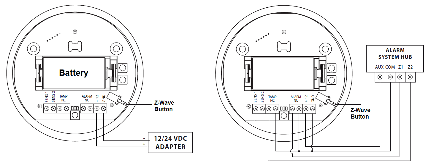
Switching to a constant current powering mode:
- Exclude a sensor from the Z-Wave network.
- Connect constant current power source (12 / 24 VDC) to +12 and GND terminals observing wiring (figure 1).
- Include the Fibaro Flood Sensor into the Z-Wave network.
In constant powering mode a sensor may operate without a battery. Installing a battery is recommended though, as it will serve as an emergency power source. When constant power fails, sensor will automatically shift to an emergency mode. All reports, including flood and temperature, will be sent immediately, but it will not be possible to modify the configuration or association settings until constant power returns. If a sensor served as a signal repeater for other Z-Wave devices, in emergency mode signal repeating function will be deactivated.
Note: Fibaro Flood Sensor will automatically exit emergency mode once 12/24 VDC at +12 and GND terminals is detected and the device wakes up after detecting an event, i.e. flood alarm, temperature report, tilt, or manual wake up using button.
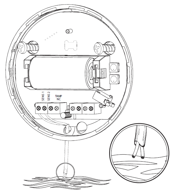
The Flood Sensor can also be used with an additional extended wire for the water sensor. Drill a hole into the casing and connect the wire as shown in figure 2.
Product Usage
Fibaro Flood Sensor has two sensors built in - flood and temperature sensors, meaning it"s a multichannel device. In the Z-Wave network"s main controller the Sensor will be shown as two devices.
Through an association Fibaro Flood Sensor may control another Z-Wave network device, e.g. a Dimmer, Relay Switch, Roller Shutter, RGBW Controller, Wall Plug, or a scene.
Z-Wave Range Test
Fibaro Flood Sensor has a built in Z-Wave network range test for the main controller. Follow the instruction to test the main controller"s range:
- Press and hold a TMP button for 10 - 15 seconds, until a LED indicator colour changes to violet.
- Release the TMP button.
- Click the TMP button again.
- LED indicator will signal the Z-Wave network range (see description below).
- To exit the Range Tester click the TMP button.
Z-Wave Range Tester signaling modes:
LED Indicator pulsing green - Fibaro Flood Sensor attempts to directly communicate with the main controller. If the direct communication attempt fails, the sensor will try routed communication, through other devices, which will be signaled with LED Indicator blinking yellow.
LED Indicator glowing green - Fibaro Flood Sensor directly communicating with the main controller.
LED Indicator pulsing yellow - Fibaro Flood Sensor tries to establish routed connection with the main controller, through intermediary devices.
LED Indicator glowing yellow - Fibaro Flood Sensor communicates with the main controller through other, intermediary devices. After two seconds the Sensor will retry to directly connect to the main controller, which will be signaled with the Indicator pulsing green.
LED Indicator pulsing violet - Fibaro Flood Sensor communicates at the range limit. If connection proves successful it will be confirmed with a yellow glow. It"s not recommended to use the sensor at the range limit.
LED Indicator glowing red - Fibaro Flood Sensor unable to connect to the main controller directly or through another Z-Wave network nodes.
| Reset to factory default | Reset procedure deletes EPROM"s memory, including all information on the Z-Wave network and the main controller. Fibaro Flood Sensor"s reset procedure: 1. Make sure the Sensor is powered. 2. Press and hold a TMP button for 15 - 20 seconds. LED indicator glows yellow to confirm entering 4th sub-menu. 3. Release the TMP button. 4. Click the TMP button, once. 5. The LED indicator glowing red and then turning off will confirm a successful reset. Reset completion will be confirmed by an acousic signal, same as at the power source connection. |
| Inclusion | Make sure that your Z-Wave Controller is in the Inclusion-/Exclusion-Mode. Tripple click the Z-Wave button inside the case to confirm the process. |
| Exclusion | Make sure that your Z-Wave Controller is in the Inclusion-/Exclusion-Mode. Tripple click the Z-Wave button inside the case to confirm the process. |
| NIF | Tripple click on the Z-Wave button inside the case or a detection by one of the sensors will send a Node Information Frame. |
| Wakeup | Tripple click on the Z-Wave button inside the case will wake up the device. |
| Protection | XXXProtection |
| FirmwareUpdate | XXXFirmwareUpdate |
| SetAssociation | XXXSetAssociation |
Association Groups:
| Group Number | Maximum Nodes | Description |
|---|---|---|
| 1 | 1 | Lifeline - reports the device status and allows for assigning single device only (main controller by default) |
| 2 | 5 | Flood Control - devices in this group will be switched on or off when flood status changes (done via BASIC SET command frames) |
| 3 | 5 | Flood Alarm - is assigned to the device status – devices in this group will receive notification about flood detection or cancellation. Useful for devices that can trigger alarms. |
| 4 | 5 | Tamper Alarm - is assigned to the TMP button and tilt sensor – devices in this group will receive a notification when the sensor is moved or the cover is taken off (which normally holds the button). Useful for devices that can trigger alarms. Functionality can be altered by parameter 74. |
Configuration Parameters
Parameter 1: Alarm cancellation delay
Determines time period (in seconds) by which a Flood Sensor will retain the flood state after the flooding itself has ceased. The sensor will keep on reporting flooding to the main controller. This parameter setting does not affect acoustic and visual alarms, which turn off immediately after flooding ceases. Size: 2 Byte, Default Value: 0
| Setting | Description |
|---|---|
| 0 - 3600 | in seconds |
Parameter 2: Acoustic and visual signals On / Off in case of flooding
Parameter allows for increasing a battery life. Setting changes will not affect the sensor’s communication with the main controller – commands to association groups, alarms and reports will still be sent. Size: 1 Byte, Default Value: 3
| Setting | Description |
|---|---|
| 0 | acoustic and visual alarms inactive |
| 1 | acoustic alarm inactive, visual alarm active |
| 2 | acoustic alarm active, visual alarm inactive |
| 3 | acoustic and visual alarms active |
Parameter 7: Forced dimming level sent to 1-st association group devices
Determines the requested “on” level to be sent to devices from 2nd association group upon flood event. The value of 255 allows for turning a device on. In case of a Dimmer it means turning it on with the last memorized state, e.g. Dimmer set to 30% and turned off, turned on again using 255 command is turned on with last state i.e. 30%. Size: 1 Byte, Default Value: 255
| Setting | Description |
|---|---|
| 1 - 99 | requested level |
| 255 | turn a device on |
Parameter 9: Alarm cancelling or turning a device off (Basic) command frame deactivation
This setting decides whether device turn off commands and alarm cancellation notifications will be sent to devices in 2nd and 3rd association groups (respectively)
Setting the parameter’s value to 0 disables sending these two commands to associated devices. This means that these devices WILL NOT be informed when the flooding has ceased. It is still possible to cancel alarms in 3rd association group by choosing second (green) menu position.
Size: 1 Byte, Default Value: 1
| Setting | Description |
|---|---|
| 0 | Alarm (flooding) cancellation inactive |
| 1 | Alarm (flooding) cancellation active |
Parameter 10: Temperature measurement interval
Time interval (in seconds) between consecutive measurements of battery level and temperature (done by built-in temperature sensor). If the temperature differs from previously reported by a value determined in parameter 12, it will be reported to the Z-Wave controller.
The parameter determines time interval, in seconds, at which a Flood Sensor measures and reports ambient temperature and battery level.
If a temperature value will differ from previously reported by a value determined in parameter 12 (e.g. P12 = 50, i.e. temperatures differ by 0.5°C), new temperature value will be reported. If a battery level changes, the device will report a battery status change – Battery Report.
In battery mode more significant battery level changes will be reported. Short time intervals mean more frequent communication, which results in shortened battery life.
After consecutive FAILED and SUCCESSFUL communication attempts, the Sensor will go to standby mode.
| Setting | Description |
|---|---|
| 1 - 65535 | in seconds |
Parameter 12: Temperature measurement hysteresis
Determines a minimum temperature change value (insensitivity level), resulting in a temperature report being sent to the main controller, according to the Parameter 10 settings. Size: 2 Byte, Default Value: 50
| Setting | Description |
|---|---|
| 1 - 1000 | each 0.01°C |
Parameter 50: Low temperature alarm threshold
The parameter stores a temperature value, below which LED indicator blinks with a colour determined by a Parameter 61 settings. By default the LED indicator blinks blue.
Note: The main controller does not interpret negative numbers as decimals. That’s why read value may be different than entered. Negative numbers are coded in U2 standard.
Size: 2 Byte, Default Value: 1500
| Setting | Description |
|---|---|
| -10000 - +10000 | each 0.01°C |
Parameter 51: High temperature alarm threshold
The parameter stores a temperature value, above which LED indicator blinks with a colour determined by the Parameter 62 settings. By default the LED indicator blinks red.
Note: The main controller does not interpret negative numbers as decimals. That’s why read value may be different than entered. Negative numbers are coded in U2 standard.
Size: 2 Byte, Default Value: 3500
| Setting | Description |
|---|---|
| -10000 - +10000 | each 0.01°C |
Parameter 61: Low temperature alarm indicator LED colour
Parameter stores RGB colour value.
Note: A main controller interprets colours as a sum of it component colours value. Each colours value is a number from 0 to 255.
Example:
Indicated colour = 65536 * RED value + 256 * GREEN value + BLUE value
| Setting | Description |
|---|---|
| 0 - 16777215 | Value |
Parameter 62: High temperature alarm indicator LED colour
Parameter stores RGB colour value.
Note: A main controller interprets colours as a sum of it component colours value. Each colours value is a number from 0 to 255.
Example:
Indicated colour = 65536 * RED value + 256 * GREEN value + BLUE value
| Setting | Description |
|---|---|
| 0 - 16777215 | Value |
Parameter 63: Managing a LED indicator under standard operation
Parameter determines LED indicatoru2019s operation. Set to 0 turns the indicator off, saving a battery life Size: 1 Byte, Default Value: 2
| Setting | Description |
|---|---|
| 0 | LED indicator doesnt indicate the temperature |
| 1 | LED indicator indicates the temperature (blink) every Temperature Measurement Interval (Parameter 10, constant current and battery) or Wake Up Interval (battery mode) |
| 2 | LED indicator indicates the temperature continuously, only in constant power mode |
Parameter 73: Temperature measurement compensation
Parameter stores a temperature value to be added to or deducted from the current temperature measured by internal temperature sensor in order to compensate the difference between air temperature and temperature at the floor level. Size: 2 Byte, Default Value: 0
| Setting | Description |
|---|---|
| - 10000 - +10000 | Value in °C step 0,01°C |
Parameter 74: Alarm frame sent to 2-nd Association Group activation
parameter to device wich sensors send Alarm to 2. association group Size: 1 Byte, Default Value: 2
| Setting | Description |
|---|---|
| 0 | tamper alarms inactive |
| 1 | button tamper alarm active |
| 2 | movement tamper alarm active |
| 3 | button and movement tampers alarm active |
Parameter 75: Visual and audible alarms duration
The device is capable of automatically turning off alarm signalization after a certain amount of time. Long lasting alarm may reduce battery life, when constantly signalized.
The parameter determines time after which alarm will become “quiet” – still active but the device will go into battery saving mode. Visual or acoustic alarm will be reactivated after time specified in the parameter 76. When alarm status ceases, alarm will be turned off immediately.
The value of 0 means visual and acoustic alarms are active indefinitely. In battery power mode the Sensor will never go to sleep which may shorten battery life significantly.
Note: The parameter is ignored when Parameter 2 is set to 0.
| Setting | Description |
|---|---|
| 0 | alarms active indefinitely |
| 1 - 65535 | time in seconds |
Parameter 76: Alarm frame / Basic Set frame retransmission time when retaining flood alarm
Parameter determines a time period after which an alarm will be turned back on (in case it was turned off by parameter 75 setting). It will also resend commands to 2nd and 3rd association groups as if the alarm was detected again.
Note: In case a time period set in parameter 76 is shorter than the one specified in parameter 75, the device will not quiet the alarm, it will remain active.
Size: 2 Byte, Default Value: 0
| Setting | Description |
|---|---|
| 0 | alarm reactivation inactive |
| 1 - 65535 | time in seconds |
Parameter 77: Flood sensor functionality turned off
Allows for turning off the internal flood sensor. Tamper and built in temperature sensor will remain active. Size: 1 Byte, Default Value: 0
| Setting | Description |
|---|---|
| 0 | Default flood sensor operation (flood detection, reactions) |
| 1 | Built in flood sensor TURNED OFF (doesnt change its state in the main controller, doesnut send Alarms and Basic Set frames with flood state changes. Always visible in the main controller as turned off) |
Parameter 78: Associations in Z-Wave network security mode
This parameter defines how commands are sent in specified association groups: as secure or non-secure. Parameter is active only in Z-Wave network security mode. It does not apply to 1st “Lifeline “group. Size: 1 Byte, Default Value: 7
| Setting | Description |
|---|---|
| 0 | none of the groups sent as secure |
| 1 | 2nd group ”Control” sent as secure |
| 2 | 3rd group ”Alarm” sent as secure |
| 4 | 4th group „Tamper” sent as secure |
| 7 | all sent as secure |
Technical Data
| Dimensions | 72 x 28 mm |
| Weight | 60 gr |
| Hardware Platform | ZM5202 |
| EAN | 5902020528357 |
| IP Class | IP 20 |
| Voltage | 12-24V DC |
| Battery Type | 1 * CR123A |
| Device Type | Flood Sensor |
| Firmware Version | 03.02 |
| Z-Wave Version | 04.05 |
| Certification ID | ZC10-18015963 |
| Z-Wave Product Id | 0x010f.0x0b01.0x1003 |
| Frequency | Europe - 868,4 Mhz |
| Maximum transmission power | 5 mW |