Fibaro Group
FIBARO Motion Sensor V3.2
SKU: FIBEFGMS-001-ZW5


Quickstart
This is a
1. Open the sensor’s casing by turning the cover counter-clockwise. Enclosure lock is marked with a dot.
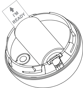
2. Unlock battery by removing “I"m ready” stripe.
3. Make sure the device is located within the direct range of the main controller.
4. Set the main controller into learning mode (see main controller’s operating manual).
5. Quickly, triple click the B-button - LED diode will glow blue to confirm setting into learning mode.
6. Fibaro Motion Sensor will be detected and included into the Z-Wave network. Wait for the main controller to configure the sensor.
7. If necessary, wake up the Motion Sensor by clicking the B-button.
8. Close the sensor’s casing and install the device in desired place.
Important safety information
Please read this manual carefully. Failure to follow the recommendations in this manual may be dangerous or may violate the law. The manufacturer, importer, distributor and seller shall not be liable for any loss or damage resulting from failure to comply with the instructions in this manual or any other material. Use this equipment only for its intended purpose. Follow the disposal instructions. Do not dispose of electronic equipment or batteries in a fire or near open heat sources.What is Z-Wave?
Z-Wave is the international wireless protocol for communication in the Smart Home. This device is suited for use in the region mentioned in the Quickstart section.
Z-Wave ensures a reliable communication by reconfirming every message (two-way communication) and every mains powered node can act as a repeater for other nodes (meshed network) in case the receiver is not in direct wireless range of the transmitter.
This device and every other certified Z-Wave device can be used together with any other certified Z-Wave device regardless of brand and origin as long as both are suited for the same frequency range.
If a device supports secure communication it will communicate with other devices secure as long as this device provides the same or a higher level of security. Otherwise it will automatically turn into a lower level of security to maintain backward compatibility.
For more information about Z-Wave technology, devices, white papers etc. please refer to www.z-wave.info.
Product Description
FIBARO Motion Sensor is a highly advanced ultra-small, battery powered multi-sensor. This device detects movement, measures the current ambient temperature, intensity of the light and thanks to built-in accelerometer detects vibrations. FIBARO Motion Sensor is a completely wireless and mobile device. Depending on user-defined situation in the settings panel it’s eye will shine in different colours, alerting you whenever the temperature and light intensity changes, or when it detects the movement in the room. The battery can last up to 2 years while its level is automatically reported to the central unit. The notification is being sent to the central hub when the battery level approaches to critical.
Prepare for Installation / Reset
Please read the user manual before installing the product.
In order to include (add) a Z-Wave device to a network it must be in factory default state. Please make sure to reset the device into factory default. You can do this by performing an Exclusion operation as described below in the manual. Every Z-Wave controller is able to perform this operation however it is recommended to use the primary controller of the previous network to make sure the very device is excluded properly from this network.
Reset to factory default
This device also allows to be reset without any involvement of a Z-Wave controller. This procedure should only be used when the primary controller is inoperable.
1. Make sure the battery works and it’s correctly placed.
2. Press and hold the B-button for 4-6 seconds until the LED glows yellow signaling the 2nd option of the menu mode.
3. Release the B-button.
4. Again, press the B-button briefly. Successful reset will be confirmed with the LED changing colour to red and fading.
Safety Warning for Batteries
The product contains batteries. Please remove the batteries when the device is not used. Do not mix batteries of different charging level or different brands.
Installation
Basic activation
1. Open the sensor’s casing by turning the cover counter-clockwise. Enclosure lock is marked with a dot.
2. Unlock battery by removing “I’m ready” stripe.
3. Include the device into the Z-Wave network. Note that the inclusion process may be performed ONLY in direct range of the main controller.
4. Install the sensor’s holder in desired location.
5. Insert the Motion Sensor in its holder.
6. Test the sensor’s operation – check whether the LED diode indicates motion detection.
7. Test the Z-Wave network assuring the device is within range.
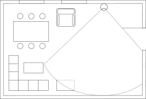
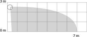
Detection area and working conditions
FIBARO Motion Sensor has to be installed in a corner of the room or perpendicularly to the doors.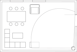
Actual range of the sensor can be influenced by environment conditions. Should false motion alarms be reported, check for any moving objects within the sensor’s detection area, such as trees blowing in the wind, cars passing by, windmills. False motion alarms may be caused by moving masses of air and heat as well. If the device keeps on reporting false alarms, despite eliminating all of the above-mentioned factors, install the device in another place.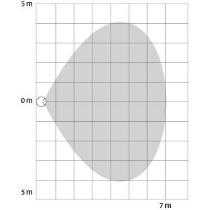
Installation notes
FIBARO Motion Sensor cannot be pointed at any source of heat (e.g. radiators, fireplaces, cookers, etc.) or at any source of light (direct sunlight, lamps).
It is not recommended to install the Motion Sensor in places prone to drafts and rooms with rapid fluctuations in air temperature.
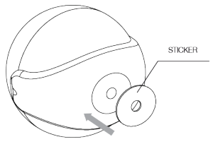
Sensor can be mounted using the included screw or the sticker.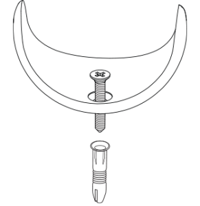
Inclusion/Exclusion
On factory default the device does not belong to any Z-Wave network. The device needs to be added to an existing wireless network to communicate with the devices of this network. This process is called Inclusion.
Devices can also be removed from a network. This process is called Exclusion. Both processes are initiated by the primary controller of the Z-Wave network. This controller is turned into exclusion respective inclusion mode. Inclusion and Exclusion is then performed doing a special manual action right on the device.
Inclusion
Quickly, three times press the B-button – LED diode will glow blue to confirm setting into learning mode.Exclusion
Quickly, three times press the B-button – LED diode will glow blue to confirm setting into learning mode.Product Usage
Menu
FIBARO Motion Sensor is equipped with the MENU providing direct control over the device.
Press and hold the B-button for at least 3 seconds to enter MENU.
Inside MENU, each of the positions will be signalled with a LED colour:
- VIOLET – Z-Wave network’s range test
- YELLOW – sensor reset
Release the B-button to choose the desired function and confirm your choice with the B-button click.
FIBARO Motion Sensor is equipped with a LED diode, signalling sensor’s operating modes and alarms. In addition the visual indicator may inform of the Z-Wave network range and the current temperature.
Visual indicator signalling modes:
- Motion Alarm’s colour will vary depending on the temperature. The colour and the signalling mode can be set in parameter 80.
- Tamper alarm is signalled with an alternating blinking in red – blue – white.
- The Z-Wave Node Info command frame is signalled with glowing in blue. Node Info command frame is sent each time the device wakes up.
Range test
FIBARO Motion Sensor has a built-in Z-Wave network main controller’s range tester.
Note: To make Z-Wave range test possible, the device must be added to the Z-Wave controller. Testing may stress the network, so it is recommended to perform the test only in special cases.
Follow the below instructions to test the main controller’s range:
- Press and hold the B-button until the visual indicator glows violet.
- Release the B-button.
- Press the B-button again, briefly.
- Visual indicator will indicate the Z-Wave network’s range (range signalling modes described below).
- To exit Z-Wave range test, press the B-button briefly.
Z-Wave range tester signalling modes:
Visual indicator pulsing green – the Motion Sensor attempts to establish a direct communication with the main controller. If a direct communication attempt fails, the device will try to establish a routed communication, through other modules, which will be signalled by visual indicator pulsing yellow.
Visual indicator glowing green – the Motion Sensor communicates with the main controller directly.
Visual indicator pulsing yellow – the Motion Sensor tries to establish a routed communication with the main controller through other modules (repeaters).
Visual indicator glowing yellow – the Motion Sensor communicates with the main controller through the other modules. After 2 seconds the device will retry to establish a direct communication with the main controller, which will be signalled with visual indicator pulsing green.
Visual indicator pulsing violet – the Motion Sensor does communicate at the maximum distance of the Z-Wave network. If connection proves successful it will be confirmed with a yellow glow. It is not recommended to use the device at the range limit.
Visual indicator glowing red – the Motion Sensor is not able to connect to the main controller directly or through another Z-Wave network device (repeater).
Note: Communication mode of the Motion Sensor may switch between direct and one using routing, especially if the device is on the limit of the direct range.
Communication to a Sleeping device (Wakeup)
This device is battery operated and turned into deep sleep state most of the time to save battery life time. Communication with the device is limited. In order to communicate with the device, a static controller C is needed in the network. This controller will maintain a mailbox for the battery operated devices and store commands that can not be received during deep sleep state. Without such a controller, communication may become impossible and/or the battery life time is significantly decreased.
This device will wakeup regularly and announce the wakeup state by sending out a so called Wakeup Notification. The controller can then empty the mailbox. Therefore, the device needs to be configured with the desired wakeup interval and the node ID of the controller. If the device was included by a static controller this controller will usually perform all necessary configurations. The wakeup interval is a tradeoff between maximal battery life time and the desired responses of the device. To wakeup the device please perform the following action: The Motion Sensor will wake up at a defined time interval and will ALWAYS try to communicate with the main controller. There is a possibility to wake up the device manually by clicking the B-button.
Quick trouble shooting
Here are a few hints for network installation if things dont work as expected.
- Make sure a device is in factory reset state before including. In doubt exclude before include.
- If inclusion still fails, check if both devices use the same frequency.
- Remove all dead devices from associations. Otherwise you will see severe delays.
- Never use sleeping battery devices without a central controller.
- Dont poll FLIRS devices.
- Make sure to have enough mains powered device to benefit from the meshing
Association - one device controls an other device
Z-Wave devices control other Z-Wave devices. The relationship between one device controlling another device is called association. In order to control a different device, the controlling device needs to maintain a list of devices that will receive controlling commands. These lists are called association groups and they are always related to certain events (e.g. button pressed, sensor triggers, ...). In case the event happens all devices stored in the respective association group will receive the same wireless command wireless command, typically a 'Basic Set' Command.
Association Groups:
| Group Number | Maximum Nodes | Description |
|---|---|---|
| 1 | 1 | Lifeline - reports the device status and allows for assigning single device only (main controller by default). |
| 2 | 5 | Motion - is assigned to the motion sensor - sends motion detection and alarm cancellation frames to the associated devices. |
| 3 | 5 | Tamper - is assigned to the tamper - sends tamper alarm and alarm cancellation frames to the associated devices. |
| 4 | 5 | Motion ZW3 - is assigned to the motion sensor - sends motion detection and alarm cancellation frames to the associated devices. Provides backward compatibility with controllers not supporting Z-Wave+ protocol. |
| 5 | 5 | Tamper ZW3 - is assigned to the tamper - sends tamper alarm and alarm cancellation frames to the associated devices. Provides backward compatibility with controllers not supporting Z-Wave+ protocol. |
Configuration Parameters
Z-Wave products are supposed to work out of the box after inclusion, however certain configuration can adapt the function better to user needs or unlock further enhanced features.
IMPORTANT: Controllers may only allow configuring signed values. In order to set values in the range 128 ... 255 the value sent in the application shall be the desired value minus 256. For example: To set a parameter to 200 it may be needed to set a value of 200 minus 256 = minus 56. In case of a two byte value the same logic applies: Values greater than 32768 may needed to be given as negative values too.
Parameter 1: MOTION SENSORS SENSITIVITY
The lower the value, the more sensitive the PIR sensor. Size: 2 Byte, Default Value: 15
| Setting | Description |
|---|---|
| 8 - 255 | Value |
Parameter 2: MOTION SENSORu2019S BLIND TIME (INSENSITIVITY)
Period of time through which the PIR sensor is blind (insensitive) tomotion. After this time period the PIR sensor will be again able todetect motion. The longer the insensitivity period, the longer the battery life. If the sensor is required to detect motion quickly, the timeperiod may be shortened. The time of insensitivity should be shorterthat the time period set in parameter 6 (cancellation delay). Size: 1 Byte, Default Value: 15
| Setting | Description |
|---|---|
| 0 - 15 | (0,5-8 seconds) Formula to calculate the time: time [s] = 0.5 x (value + 1) |
Parameter 3: PIR sensors PULSE COUNTER
Sets the number of moves required for the PIR sensor to reportmotion. The higher the value, the less sensitive the PIR sensor. Its not recommended to modify this parameter settings. Size: 1 Byte, Default Value: 1
| Setting | Description |
|---|---|
| 0 - 3 | (1 - 4 pulses) Formula to calculate the number of pulses: pulses = (value + 1) |
Parameter 4: PIR sensors WINDOW TIME
Period of time during which the number of moves set in parameter 3must be detected in order for the PIR sensor to report motion. Thehigher the value, the more sensitive the PIR sensor. Its notrecommended to modify this parameter setting. Size: 1 Byte, Default Value: 2
| Setting | Description |
|---|---|
| 0 - 3 | Formula to calculate the time: time [s] = 4 x (value + 1) |
Parameter 6: MOTION ALARM CANCELLATION DELAY
Motion alarm will be cancelled in the main controller and theassociated devices after the period of time set in this parameter. Anymotion detected during the cancellation delay time countdown willresult in the countdown being restarted. In case of small values,below 10 seconds, the value of parameter 2 must be modified (PIRsensors Blind Time). Size: 2 Byte, Default Value: 30
| Setting | Description |
|---|---|
| 1 - 32767 | (1-32767 seconds) |
Parameter 8: PIR SENSOR OPERATING MODE
The parameter determines the part of day in which the PIR sensor will be active. This parameter influences only the motion reports andassociations. Tamper, light intensity and temperature measurementswill be still active, regardless of this parameter settings. Size: 1 Byte, Default Value: 0
| Setting | Description |
|---|---|
| 0 | PIR sensor always active |
| 1 | PIR sensor active during the day only |
| 2 | PIR sensor active during the night only |
Parameter 9: NIGHT / DAY
The parameter defines the difference between night and day, interms of light intensity, used in parameter 8. Size: 2 Byte, Default Value: 200
| Setting | Description |
|---|---|
| 1 - 32767 | (1-32767 lux) |
Parameter 12: BASIC COMMAND CLASS FRAMES CONFIGURATION
The parameter determines the command frames sent in 1-stassociation group, assigned to PIR sensor.Values of BASIC ON and BASIC OFF command frames may bemodified by dedicated parameters (14 and 16). Size: 1 Byte, Default Value: 0
| Setting | Description |
|---|---|
| 0 | BASIC ON and OFF command frames sent in Basic Command Class. |
| 1 | only the BASIC ON command frame sent in Basic Command Class. |
| 2 | only the BASIC OFF command frame sent in Basic Command Class. |
Parameter 14: BASIC ON command frame value
The command frame sent at the moment of motion detection. Further motion detections, during the cancellation time, will not result in sending the association. Size: 2 Byte, Default Value: 255
| Setting | Description |
|---|---|
| 0 - 255 | Value |
Parameter 16: BASIC OFF command frame value
The command frame sent at the moment of motion alarm cancellation, after cancellation delay time specified in parameter 6. Size: 2 Byte, Default Value: 0
| Setting | Description |
|---|---|
| 0 - 255 | Value |
Parameter 18: Associations in Z-Wave network Security Mode
This parameter defines how commands are sent in specified association groups: as secure or non-secure. Parameter is active only in Z-Wave network security mode. It does not apply to 1st group “Lifeline”. Size: 1 Byte, Default Value: 15
| Setting | Description |
|---|---|
| 0 | none of the groups sent as secure |
| 1 | 2nd group sent as secure |
| 2 | 3rd group sent as secure |
| 4 | 4th group sent as secure |
| 8 | 5th group sent as secure |
Parameter 20: TAMPER SENSITIVITY
The parameter determines the chages in forces acting on the Fibaro Motion Sensor resulting in tamper alarm being reported - g-force acceleration. Size: 1 Byte, Default Value: 20
| Setting | Description |
|---|---|
| 0 - 121 | (0,08 - 2g; multiply by 0,016g; 0 = tamper inactive) |
Parameter 22: TAMPER ALARM CANCELLATION DELAY
Time period after which a tamper alarm will be cancelled. Anothertampering detected during the countdown to cancellation will not extend the delay. Size: 2 Byte, Default Value: 30
| Setting | Description |
|---|---|
| 1 - 32767 | (1-32767 seconds) |
Parameter 24: TAMPER OPERATING MODES
This parameter determines function of the tamper and sent reports. It is an advanced feature serving much more functions than just detection of tampering. Size: 1 Byte, Default Value: 0
| Setting | Description |
|---|---|
| 0 | Only tamper (default) |
| 1 | Tamper and earthquake detector. Function may be used as a simple seismograph. Two reports including the strength of shock are always sent. First, right after the detection and second (value=0) after tamper alarm cancellation delay time. |
| 2 | Tamper and orientation in space. Three reports are sent right after tamper alarm cancellation delay time. |
Parameter 25: TAMPER CANCELLATION REPORTS
This parameter allows to disable cancellation of the tamper alarm. Size: 1 Byte, Default Value: 1
| Setting | Description |
|---|---|
| 0 | Do not send tamper cancellation report |
| 1 | Send tamper cancellation report |
Parameter 28: TAMPER ALARM BROADCAST MODE
The parameter determines whether the tamper alarm frame will orwill not be sent in broadcast mode. Alarm frames sent in broadcastmode can be received by all of the devices within communicationrange (if they accept such frames). When Fibaro Motion Sensor is operating in protected mode (secure mode), the value should remaindefault. Device operating in protected mode doesnt send frames inbroadcast mode. Size: 1 Byte, Default Value: 0
| Setting | Description |
|---|---|
| 0 | Tamper alarm reported to association groups. |
| 1 | Tamper alarm reported in broadcast mode to 3rd association group. |
Parameter 29: TAMPER ALARM BROADCAST MODE
The parameter determines whether the tamper alarm frame will orwill not be sent in broadcast mode. Alarm frames sent in broadcastmode may be received by all of the devices within communicationrange (if they accept such frames). When Fibaro Motion Sensor isrunning in protected mode (secure mode), the value should remaindefault. Device operating in protected mode do not send frames inbroadcast mode. Size: 1 Byte, Default Value: 0
| Setting | Description |
|---|---|
| 0 | Tamper alarm reported to association groups. |
| 1 | Tamper alarm reported in broadcast mode to 5th association group. |
Parameter 40: ILLUMINATION REPORT THRESHOLD
The parameter determines the change in light intensity levelresulting in illumination report being sent to the main controller. Size: 2 Byte, Default Value: 200
| Setting | Description |
|---|---|
| 0 - 32767 | (1-32767 lux; 0=reports are not sent) |
Parameter 42: ILLUMINATION REPORTS INTERVAL
Time interval between consecutive illumination reports. The reportsare sent even if there are no changes in the light intensity.CAUTIONFrequent reports will shorten the battery life.Parameter value under 5 may result in blocking thetemperature reports. Size: 2 Byte, Default Value: 3600
| Setting | Description |
|---|---|
| 0 - 32767 | (1-32767 seconds; 0 = no reports) |
Parameter 60: TEMPERATURE REPORT THRESHOLD
The parameter determines the change in level of temperatureresulting in temperature report being sent to the main controller. Size: 2 Byte, Default Value: 10
| Setting | Description |
|---|---|
| 0 - 225 | (0,1-25,5[C],; 0 = reports are not sent) |
Parameter 62: INTERVAL OF TEMPERATURE MEASURING
The parameter determines how often the temperature will bemeasured. The shorter the time, the more frequently the temperaturewill be measured, but the battery life will shorten.
CAUTION When parameter value is set to 0, the temperaturemeasurements may be performed at the devicewake-up.
Size: 2 Byte, Default Value: 900
| Setting | Description |
|---|---|
| 0 - 32767 | (1 - 32767 seconds; 0 = temperature will not be measured) |
Parameter 64: TEMPERATURE REPORTS INTERVAL
The parameter determines how often the temperature reports will besent to the main controller.
CAUTION Frequent reports will shorten the battery life.Parameter value under 5 may result in blocking theillumination reports.
Size: 2 Byte, Default Value: 0
| Setting | Description |
|---|---|
| 0 - 32767 | (1 - 32767 seconds; 0 = no reports) |
Parameter 66: TEMPERATURE OFFSET
The value to be added to the actual temperature, measured by thesensor (temperature compensation). Size: 2 Byte, Default Value: 0
| Setting | Description |
|---|---|
| -1000 - 1000 | (-100[C] - 100[C]) |
Parameter 80: LED SIGNALING MODE
The parameter determines the way in which LED diode behavesafter motion has been detected.0. LED inactive.1. LED colour depends on the temperature. Set by parameters86 and 87.2. Flashlight mode - LED glows in white for 10 seconds.3. White.4. Red.5. Green.6. Blue.7. Yellow.8. Cyan.9. Magenta.10. LED colour depends on the temperature. Set by parameters86 and 87.11. Flashlight mode - LED glows in white through 10 sec. Eachnext detected motion extends the glowing by next 10 seconds.12. White.13. Red.14. Green.15. Blue.16. Yellow.17. Cyan18. Magenta19. LED colour depends on the temperature. Set by parameters86 and 87.20. White21. Red22. Green23. Blue24. Yellow25. Cyan26. Magenta Size: 1 Byte, Default Value: 10
| Setting | Description |
|---|---|
| 1 - 9 | single long blink at the moment of reporting motion. No other motion will be indicated until alarm is cancelled. |
| 10 - 18 | single long blink at the moment of reporting motion and one short blink each time the motion is detected again. |
| 19 - 26 | single long blink at the moment of reporting motion and two short blinks each time the motion is detected again. |
Parameter 81: LED BRIGHTNESS
The parameter determines the brightness of LED when indicatingmotion. Size: 1 Byte, Default Value: 50
| Setting | Description |
|---|---|
| 0 - 100 | (1 - 100%; 0 = brightness determined by the ambient lighting - see parameters 82 and 83) |
Parameter 82: AMBIENT ILLUMINATION LEVEL BELOW WHICH LED BRIGHTNESS IS SET TO 1%
The parameter is relevant only when the parameter 81 is set to 0.CAUTIONThe value of parameter 83 must be higher than thevalue of parameter 82. Size: 2 Byte, Default Value: 100
| Setting | Description |
|---|---|
| 0 - 32766 | (0-32766 lux) |
Parameter 83: AMBIENT ILLUMINATION LEVEL ABOVE WHICH LED BRIGHTNESS IS SET TO 100%
The parameter is relevant only when the parameter 81 is set to 0.CAUTIONThe value of parameter 83 must be higher than thevalue of parameter 82. Size: 2 Byte, Default Value: 1000
| Setting | Description |
|---|---|
| 1 - 32767 | (1-32767 lux) |
Parameter 86: MINIMUM TEMPERATURE RESULTING IN BLUE LED ILLUMINATION
This parameter is relevant only when parameter 80 has beenproperly configured.CAUTIONThe value of parameter 87 must be higher than thevalue of parameter 86. Size: 2 Byte, Default Value: 18
| Setting | Description |
|---|---|
| 0 - 255 | (0-255[C]) |
Parameter 87: MAXIMUM TEMPERATURE RESULTING IN RED LED ILLUMINATION
This parameter is relevant only when parameter 80 has beenproperly configured.CAUTIONThe value of parameter 87 must be higher than thevalue of parameter 86. Size: 2 Byte, Default Value: 28
| Setting | Description |
|---|---|
| 0 - 255 | (0-255[C]) |
Parameter 89: LED INDICATING TAMPER ALARM
Indicating mode resembles a police car (white, red and blue). Size: 1 Byte, Default Value: 1
| Setting | Description |
|---|---|
| 0 | LED does not indicate tamper alarm. |
| 1 | LED indicates tamper alarm. |
Technical Data
| Dimensions | 47x47x47 mm |
| Weight | 24 gr |
| Hardware Platform | ZM5202 |
| EAN | 5902020528579 |
| IP Class | IP 20 |
| Battery Type | 1 * CR123A |
| Device Type | Notification Sensor |
| Network Operation | Reporting Sleeping Slave |
| Z-Wave Version | 6.51.06 |
| Certification ID | ZC10-15050019 |
| Z-Wave Product Id | 0x010F.0x0801.0x1001 |
| Frequency | Europe - 868,4 Mhz |
| Maximum transmission power | 5 mW |
Supported Command Classes
- Sensor Alarm
- Application Status
- Association
- Association Group Information
- Basic
- Battery
- Sensor Binary
- Configuration
- Crc 16 Encap
- Device Reset Locally
- Firmware Update Md V3
- Manufacturer Specific
- Multi Channel Association
- Multi Command
- Sensor Multilevel
- Notification
- Powerlevel
- Security
- Version
- Wake Up
- Zwaveplus Info
Controlled Command Classes
- Basic
Explanation of Z-Wave specific terms
- Controller — is a Z-Wave device with capabilities to manage the network. Controllers are typically Gateways,Remote Controls or battery operated wall controllers.
- Slave — is a Z-Wave device without capabilities to manage the network. Slaves can be sensors, actuators and even remote controls.
- Primary Controller — is the central organizer of the network. It must be a controller. There can be only one primary controller in a Z-Wave network.
- Inclusion — is the process of adding new Z-Wave devices into a network.
- Exclusion — is the process of removing Z-Wave devices from the network.
- Association — is a control relationship between a controlling device and a controlled device.
- Wakeup Notification — is a special wireless message issued by a Z-Wave device to announces that is able to communicate.
- Node Information Frame — is a special wireless message issued by a Z-Wave device to announce its capabilities and functions.