Quickstart

This is a secure Motor Control Device (B) for XXXQFrequencyName. To run this device please connect it to your mains power supply. To add this device to your network execute the following action:
Quickly, triple click the S1 switch.


Important safety information

Please read this manual carefully. Failure to follow the recommendations in this manual may be dangerous or may violate the law. The manufacturer, importer, distributor and seller shall not be liable for any loss or damage resulting from failure to comply with the instructions in this manual or any other material. Use this equipment only for its intended purpose. Follow the disposal instructions. Do not dispose of electronic equipment or batteries in a fire or near open heat sources.

Product Description

FIBARO Roller Shutter 3 is a device designed to control roller blinds, awnings, venetian blinds, gates and other single phase, AC powered devices.

Roller Shutter 3 allows precise positioning of roller blinds or venetian blind lamellas. The device is equipped with power and energy monitoring. It allows to control connected devices either via the Z-Wave network or via a switch connected directly to it.


Installation

Installation with standard blinds:


Notes for the diagrams:

S1 – terminal for 1st switch (used to add/remove the device)
S2 – terminal for 2nd switch
Q2 – 2nd output terminal for shutter motor DOWN
Q1 – 1st output terminal for shutter motor UP
L – terminal for live lead
N – terminal for neutral lead

B – service button (used to add/remove the device and navigate the menu)

Installation of blinds with built-in driver

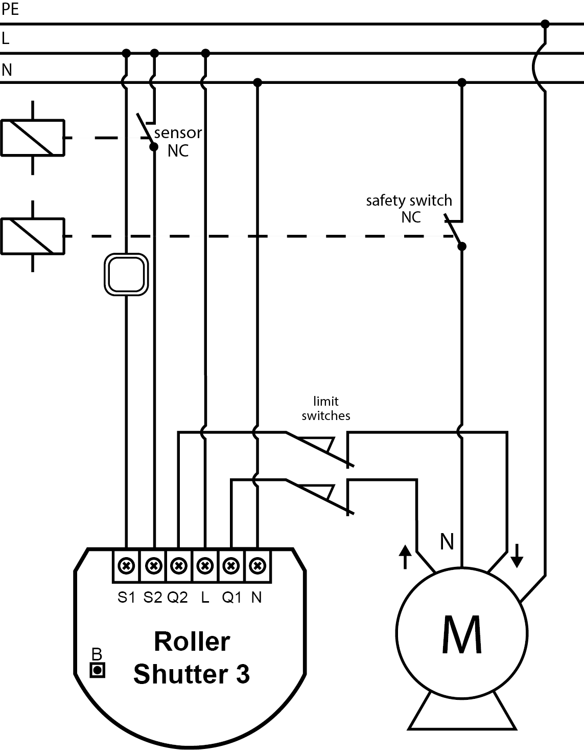
Installation of gate motors

  • Installation of the gate driver may be performed only by certified professionals.
  • The motor must be equipped with the appropriate limit switches.
  • It is recommended to connect a NC (normally closed) contact of an IR barrier to S2 terminal. Opening the contact will stop the gate.
  • In addition, it is recommended to connect an emergency stop button to the motors neutral (N) wire. In emergency, pushing the emergency stop button will cut the power and stop the gate.

Calibration 

Calibration is a process during which a device learns the position of the limit switches and a motor characteristic.

Calibration is mandatory in order for the device to correctly recognize a roller blind position.

The procedure consists of an automatic, full movement between the limit switches (up, down, and up again).

Note: If you notice the calibration process fail (e.g. it does not start, movement times are really short or highly inaccurate), adjust parameter 155 value (e.g. reduce it by half).


Standard roller blind positioning

Calibration using a connected momentary switch


  1. Make sure:
    • the device is supplied,
    • the momentary switch is connected to S1 and S2 terminals,
    • the device added to the Z-Wave network,
    • parameter 151 is set to 1 or 2.
  2. Press and hold UP or DOWN switch for at least 3 seconds
  3. Press and hold the same switch again for at least 3 seconds.
  4. Press and hold the same switch again for at least 3 seconds.
  5. The device will perform the calibration process, completing full cycle – up, down and up again.
  6. Test whether the positioning works correctly.

Calibration using the B-button

  1. Make sure:
    • the device is supplied,
    • the device added to the Z-Wave network,
    • parameter 151 is set to 1 or 2.
  2. Press and hold the B-button.
  3. Wait for the LED to glow white.
  4. Quickly release and click the B-button again.
  5. The device will perform the calibration process, completing full cycle – up, down and up again
  6. Test whether the positioning works correctly.

Calibration using parameter

  1. Make sure:
    • the device is supplied,
    • the device added to the Z-Wave network,
    • parameter 151 is set to 1 or 2.
  2. Set the parameter 150 value to 2
  3. The device will perform the calibration process, completing full cycle – up, down and up again
  4. The parameter 150 value will be set to 1 after calibration finishes.
  5. Test whether the positioning works correctly.


Slats positioning in Venetian blinds mode

Calibration using a connected momentary switch


  1. Make sure:
    • the device is supplied,
    • the momentary switch is connected to S1 and S2 terminals,
    • the device added to the Z-Wave network,
    • parameter 151 is set to 2,
    • blinds are calibrated.
  2. By default, time of transition between extreme positions is set to 150 (1.5 seconds) in parameter 152.
  3. Turn slats between extreme positions by holding UP or DOWN switch:
    • If after full cycle a blind starts moving up or down – decrease the value of parameter 152,
    • If after full cycle the slats do not reach end positions – increase the value of parameter 152,
  4. Repeat the previous step until satisfactory positioning is achieved.
  5. Test whether the positioning works correctly. Correctly configured slats should not force the blinds to move up or down.

Roller blind with built-in driver positioning

  1. Make sure:
    • the device is supplied,
    • the momentary switch is connected to S1 and S2 terminals,
    • the device added to the Z-Wave network,
    • parameter 151 is set to 5 or 6.
  2. By default, time of transition between extreme positions is set to 600 (6 seconds) in parameters 155 and 156.
  3. Move roller blinds between extreme positions by clicking UP or DOWN switch:
    • If roller blind stops before reaching top – increase the value of parameter 155,
    • If roller blind does not stop after reaching top – decrease the value of parameter 155,
    • If roller blind stops before reaching bottom – increase the value of parameter 156,
    • If roller blind does not stop after reaching bottom – decrease value of parameter 156,
  4. Repeat the previous step until satisfactory positioning is achieved.
  5. Test whether the positioning works correctly.

Product Usage

Range test

To make Z-Wave range test possible, the device must be added to the Z-Wave controller. Testing may stress the network, so it is recommended to perform the test only in special cases.

The device has a built in Z-Wave network main controller’s range tester.

Follow the below instructions to test the main controller’s range:

  1. Switch off the mains voltage (disable the fuse).
  2. Remove the device from the wall switch box.
  3. Switch on the mains voltage.
  4. Press and hold the B-button to enter the menu.
  5. Wait for the visual LED indicator to glow violet.
  6. Quickly release and click the B-button again.
  7. Visual indicator will indicate the Z-Wave network’s range (range signalling modes described below).
  8. To exit Z-Wave range test, click the B-button.

 Note: Communication mode of the device may switch between direct and one using routing, especially if the device is on the limit of the direct range.

Z-Wave range tester signaling modes:

Visual indicator pulsing green – the device attempts to establish a direct communication with the main controller. If a direct communication attempt fails, the device will try to establish a routed communication, through other modules, which will be signalled by visual indicator pulsing yellow.

Visual indicator glowing green – the device communicates with the main controller directly.

Visual indicator pulsing yellow – the device tries to establish a routed communication with the main controller through other modules (repeaters).

Visual indicator glowing yellow – the device communicates with the main controller through the other modules. After 2 seconds the device will retry to establish a direct communication with the main controller, which will be signalled with visual indicator pulsing green.

Visual indicator pulsing violet – the device does communicate at the maximum distance of the Z-Wave network. If connection proves successful it will be confirmed with a yellow glow. It’s not recommended to use the device at the range limit.

Visual indicator glowing red – the device is not able to connect to the main controller directly or through another Z-Wave network device (repeater).

 Menu

Menu allows to perform Z-Wave network actions. In order to use the menu:

  1. Switch off the mains voltage (disable the fuse).
  2. Remove the device from the wall switch box.
  3. Switch on the mains voltage.
  4. Press and hold the B-button to enter the menu.
  5. Wait for the LED to indicate the desired menu position with colour:
    • WHITE – start calibration
    • GREEN – reset energy consumption memory
    • VIOLET – start range test
    • YELLOW – reset the device
  6. Quickly release and click the B-button again.


Reset to factory default
  1. Press and hold the B-button to enter the menu.
  2. Wait for the LED indicator to glow yellow.
  3. Quickly release and click the B-button again.
  4. After few seconds the device will be restarted, which is signalled with the red LED indicator color.
Inclusion Quickly, triple click the S1 switch.
Exclusion Quickly, triple click the S1 switch.
NIF XXXNIF
Wakeup XXXWakeupDescription
Protection XXXProtection
FirmwareUpdate XXXFirmwareUpdate
SetAssociation XXXSetAssociation

Association Groups:

Group Number Maximum Nodes Description
1 1 Lifeline
2 5 Roller Shutter
3 5 Slats position control

Configuration Parameters

Parameter 20: Switch type

This parameter defines as what type the device should treat the switch connected to the S1 and S2 terminals.
This parameter is not relevant in gate operating modes (parameter 151 set to 3 or 4). In this case switch always works as a momentary and has to be connected to S1 terminal.

Size: 1 Byte, Default Value: 2

Setting Description
0 momentary switches
1 toggle switches
2 single, momentary switch (the switch should be connected to S1 terminal)

Parameter 24: Inputs orientation

This parameter allows reversing the operation of switches connected to S1 and S2 without changing the wiring.
Size: 1 Byte, Default Value: 0

Setting Description
0 default (S1 – 1st channel, S2 – 2nd channel)
1 reversed (S1 – 2nd channel, S2 – 1st channel)

Parameter 25: Outputs orientation

This parameter allows reversing the operation of Q1 and Q2 without changing the wiring (in case of invalid motor connection) to ensure proper operation.
Size: 1 Byte, Default Value: 0

Setting Description
0 default (Q1 – 1st channel, Q2 – 2nd channel)
1 reversed (Q1 – 2nd channel, Q2 – 1st channel)

Parameter 30: Alarm configuration - 1st slot

This parameter determines to which alarm frames and how the device should react. The parameters consist of 4 bytes, three most significant bytes are set according to the official Z-Wave protocol specification.

For a setting of this parameter, please refer to the manufacturer‘s manual.

Size: 4 Byte, Default Value: 0

Setting Description

Parameter 31: Alarm configuration - 2nd slot (Water)

This parameter determines to which alarm frames and how the device should react. The parameters consist of 4 bytes, three most significant bytes are set according to the official Z-Wave protocol specification.
For a setting of this parameter, please refer to the manufacturer‘s manual.

Size: 4 Byte, Default Value:

Setting Description

Parameter 32: Alarm configuration - 3rd slot (Smoke)

This parameter determines to which alarm frames and how the device should react. The parameters consist of 4 bytes, three most significant bytes are set according to the official Z-Wave protocol specification.
For a setting of this parameter, please refer to the manufacturer‘s manual.

Size: 4 Byte, Default Value:

Setting Description

Parameter 33: Alarm configuration - 4th slot (CO)

This parameter determines to which alarm frames and how the device should react. The parameters consist of 4 bytes, three most significant bytes are set according to the official Z-Wave protocol specification.For a setting of this parameter, please refer to the manufacturer‘s manual.
For a setting of this parameter, please refer to the manufacturer‘s manual.

Size: 4 Byte, Default Value:

Setting Description

Parameter 35: Alarm configuration - 5th slot (Heat)

This parameter determines to which alarm frames and how the device should react. The parameters consist of 4 bytes, three most significant bytes are set according to the official Z-Wave protocol specification.
Size: 4 Byte, Default Value:

Setting Description

Parameter 40: S1 switch - scenes sent

This parameter determines which actions result in sending scene IDs assigned to them.
Size: 1 Byte, Default Value: 0

Setting Description
1 Key pressed 1 time
2 Key pressed 2 times
4 Key pressed 3 times
8 Key hold down and key released
15 All

Parameter 42: S2 switch - scenes sent

This parameter determines which actions result in sending scene IDs assigned to them.
Size: 1 Byte, Default Value: 0

Setting Description
1 Key pressed 1 time
2 Key pressed 2 times
4 Key pressed 3 times
8 Key hold down and key released
15 All

Parameter 60: Measuring power consumed by the device itself

This parameter determines whether the power metering should include the amount of active power consumed by the device itself.
Size: 1 Byte, Default Value: 0

Setting Description
0 function inactive
1 function active

Parameter 61: Power reports - on change

This parameter determines the minimum change in consumed power that will result in sending new power report to the main controller.
For loads under 50W, the parameter is not relevant and reports are sent every 5W change.
Power reports are sent no often than every 30 seconds.

Size: 2 Byte, Default Value: 15

Setting Description
0 reports are disabled
1 - 500 change in power in %

Parameter 62: Power reports - periodic

This parameter determines in what time intervals the periodic power reports are sent to the main controller. Periodic reports do not depend on power change (parameter 61).
Size: 2 Byte, Default Value: 3600

Setting Description
0 periodic reports are disabled
30 - 32400 report interval in seconds

Parameter 65: Energy reports - on change

This parameter determines the minimum change in consumed energy that will result in sending new energy report to the main controller.
Size: 2 Byte, Default Value: 10

Setting Description
0 reports are disabled
1 - 500 (0.01 – 5 kWh) – change in energy

Parameter 66: Energy reports - periodic

This parameter determines in what time intervals the periodic energy reports are sent to the main controller. Periodic reports do not depend on energy change (parameter 65).
Size: 2 Byte, Default Value: 3600

Setting Description
0 periodic reports are disabled
30 - 32400 report interval in seconds

Parameter 150: Force calibration

By setting this parameter to 2 the device enters the calibration mode. The parameter relevant only if the device is set to work in positioning mode (parameter 151 set to 1, 2 or 4).
Size: 1 Byte, Default Value: 0

Setting Description
0 device is not calibrated
1 device is calibrated
2 force device calibration

Parameter 151: Operating mode

This parameter allows adjusting operation according to the connected device.
Size: 1 Byte, Default Value: 1

Setting Description
1 roller blind (with positioning)
2 Venetian blind (with positioning)
3 gate (without positioning)
4 gate (with positioning)
5 roller blind with built-in driver
6 roller blind with built-in driver (impulse)

Parameter 152: Venetian blind - time of full turn of the slats

For Venetian blinds (parameter 151 set to 2) the parameter determines time of full turn cycle of the slats.
For gates (parameter 151 set to 3 or 4) the parameter determines time after which open gate will start closing automatically (if set to 0, gate will not close).
The parameter is irrelevant for other modes.

Size: 5 Byte, Default Value: 150

Setting Description
0 - 90000 (0 – 900s, every 0.01s) – time of turn

Parameter 153: Set slats back to previous position

For Venetian blinds (parameter 151 set to 2) the parameter determines slats positioning in various situations.
The parameter is irrelevant for other modes.

Size: 1 Byte, Default Value: 1

Setting Description
0 slats return to previously set position only in case of the main controller operation.
1 slats return to previously set position in case of the main controller operation, momentary switch operation, or when the limit switch is reached.
2 slats return to previously set position in case of the main controller operation, momentary switch operation, when the limit switch is reached or after receiving the Switch Multilevel Stop control frame

Parameter 154: Delay motor stop after reaching end switch

For blinds (parameter 151 set to 1, 2, 5 or 6) the parameter determines the time after which the motor will be stopped after end switch contacts are closed.
For gates (parameter 151 set to 3 or 4) the parameter determines the time after which the gate will start closing automatically if S2 contacts are opened (if set to 0, gate will not close).

Size: 2 Byte, Default Value: 10

Setting Description
0 - 60 (0 – 60s) – time

Parameter 155: Motor operation detection

Power threshold to be interpreted as reaching a limit switch.
Size: 2 Byte, Default Value: 10

Setting Description
0 reaching a limit switch will not be detected
1 - 255 report interval in watt

Parameter 156: Time of up movement

This parameter determines the time needed for roller blinds to reach the top.
For modes with positioning value is set automatically during calibration, otherwise, it must be set manually.

Size: 4 Byte, Default Value: 6000

Setting Description
1 - 90000 (0.01 – 900.00s, every 0.01s) – movement time

Parameter 157: Time of down movement

This parameter determines time needed for roller blinds to reach the bottom.
For modes with positioning value is set automatically during calibration, otherwise, it must be set manually.

Size: 4 Byte, Default Value: 6000

Setting Description
1 - 90000 (0.01 – 900.00s, every 0.01s) – movement time

Technical Data

Dimensions 42.50 x 38.25 x 20.30 mm
Weight 27.83 gr
EAN 5905279987197
IP Class IP 20
Voltage 230 V
Load 1,7 A
Device Type Roller Shutter
Generic Device Class Multilevel Switch
Specific Device Class Motor Control Device (B)
Firmware Version 05.00
Z-Wave Version 06.02
Certification ID ZC10-19046413
Z-Wave Product Id 0x010f.0x0303.0x1000
Frequency Europe - 868,4 Mhz
Maximum transmission power 5 mW
EuropeRoller Shutter