Fibaro Group
FIBARO Single Switch 2
SKU: FIBEFGS-213


Quickstart
This is a
Important safety information
Please read this manual carefully. Failure to follow the recommendations in this manual may be dangerous or may violate the law. The manufacturer, importer, distributor and seller shall not be liable for any loss or damage resulting from failure to comply with the instructions in this manual or any other material. Use this equipment only for its intended purpose. Follow the disposal instructions. Do not dispose of electronic equipment or batteries in a fire or near open heat sources.What is Z-Wave?
Z-Wave is the international wireless protocol for communication in the Smart Home. This device is suited for use in the region mentioned in the Quickstart section.
Z-Wave ensures a reliable communication by reconfirming every message (two-way communication) and every mains powered node can act as a repeater for other nodes (meshed network) in case the receiver is not in direct wireless range of the transmitter.
This device and every other certified Z-Wave device can be used together with any other certified Z-Wave device regardless of brand and origin as long as both are suited for the same frequency range.
If a device supports secure communication it will communicate with other devices secure as long as this device provides the same or a higher level of security. Otherwise it will automatically turn into a lower level of security to maintain backward compatibility.
For more information about Z-Wave technology, devices, white papers etc. please refer to www.z-wave.info.
Product Description
FIBARO Switch 2 is designed to be installed in standard wall switch boxes or anywhere else where it is necessary to control electric devices. FIBARO Switch 2 allows to control connected devices either via the Z-Wave+ network or via a switch connected directly to it and is equipped with active power and energy consumption metering functionality.
Prepare for Installation / Reset
Please read the user manual before installing the product.
In order to include (add) a Z-Wave device to a network it must be in factory default state. Please make sure to reset the device into factory default. You can do this by performing an Exclusion operation as described below in the manual. Every Z-Wave controller is able to perform this operation however it is recommended to use the primary controller of the previous network to make sure the very device is excluded properly from this network.
Reset to factory default
This device also allows to be reset without any involvement of a Z-Wave controller. This procedure should only be used when the primary controller is inoperable.
- Switch off the mains voltage (disable the fuse).
- Remove the Switch 2 from the wall switch box.
- Switch on the mains voltage.
- Press and hold the B-button to enter the menu.
- Wait for the visual LED indicator to glow yellow.
- Quickly release and click the B-button again.
- After few seconds the device will be restarted, which is signalled with the red LED indicator colour.
Safety Warning for Mains Powered Devices
ATTENTION: only authorized technicians under consideration of the country-specific installation guidelines/norms may do works with mains power. Prior to the assembly of the product, the voltage network has to be switched off and ensured against re-switching.
Installation
Installation
Connecting the device in a manner inconsistent with manual may cause risk to health, life or material damage.
When connecting the device act in accordance with the following rules:
- Connect only in accordance with one of the diagrams,
- Electrical installation must be protected by overcurrent protection (fuse) of with a value not higher than 10A,
- The Switch 2 should be installed in a wall switch box compliant with a relevant national safety standards and with depth no less than 60mm,
- Electrical switches used in installation should be compliant with the relevant safety standards,
- Length of wires used to connect the control switch should not exceed 10m.
Notes for the diagrams:
S1 – terminal for 1st switch (has the function of activating the learning mode)
S2 – terminal for 2nd switch
L – terminal for live lead
Q – output terminal of the 1st channel
N – terminal for neutral lead
B – service button (used to add/remove the device and navigate the menu)
Installation of the device:
- Switch off the mains voltage (disable the fuse).
- Open the wall switch box.
- Connect with one of the diagrams below for appropriate device.
- After verifying correctness of the connection switch on the mains voltage.
- Add the device to the Z-Wave network.
- Turn off the mains voltage, then arrange the device and its antenna in a wall switch box.
- Close the wall switch box and turn on the mains voltage.
Switch connected to the S1 terminal is a master switch. It activates the basic functionality of the device (turning the first load on/off) and activates the learning mode (adding/removing). The switch connected to the S2 terminal turns on/of the second load in Double Switch 2, but is optional in Single Switch 2 and pushing it will not affect the status of the device.
After switching on the mains voltage LED indicator will signal Z-Wave network inclusion state with a colour:
GREEN - device added
RED - device not added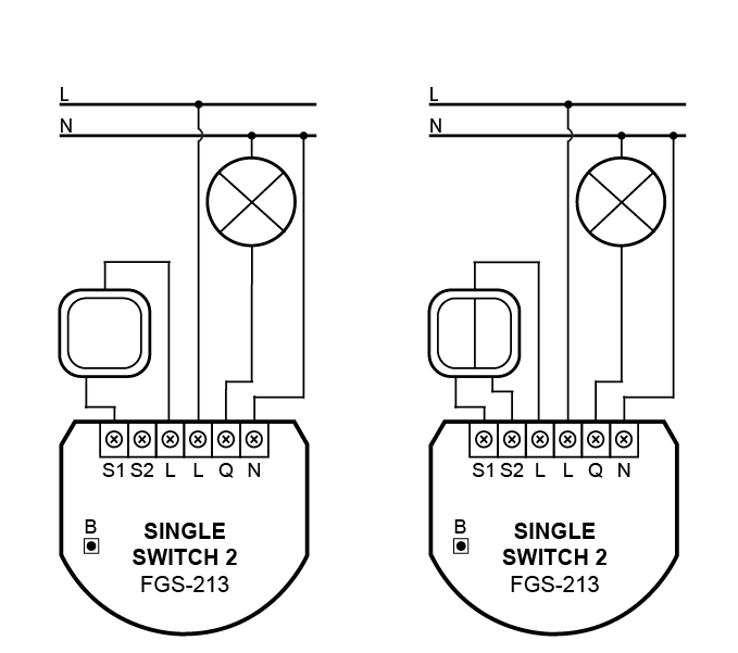
Arranging the antenna
- Locate the antenna as far from metal elements as possible (connecting wires, bracket rings, etc.) in order to prevent interferences.
- Metal surfaces in the direct vicinity of the antenna (e.g. flush mounted metal boxes, metal door frames) may impair signal reception!
- Do not cut or shorten the antenna – its length is perfectly matched to the band in which the system operates.
Inclusion/Exclusion
On factory default the device does not belong to any Z-Wave network. The device needs to be added to an existing wireless network to communicate with the devices of this network. This process is called Inclusion.
Devices can also be removed from a network. This process is called Exclusion. Both processes are initiated by the primary controller of the Z-Wave network. This controller is turned into exclusion respective inclusion mode. Inclusion and Exclusion is then performed doing a special manual action right on the device.
Inclusion
- Place the Switch 2 within the direct range of your Z-Wave controller.
- Identify the S1 switch.
- Set the main controller in (security/non-security) add mode (see the controller’s manual).
- Quickly, three times press the S1 switch or B-button
- Wait for the adding process to end.
- Successful adding will be confirmed by the Z-Wave controller’s message.
Exclusion
- Place the Switch 2 within the direct range of your Z-Wave controller.
- Identify the S1 switch.
- Set the main controller in remove mode (see the controller’s manual).
- Quickly, three times press the S1 switch or B-button
- Wait for the removing process to end.
- Successful removing will be confirmed by the Z-Wave controller’s message.
Auto-Inclusion
Beside the standard inclusion this devices supports the so called auto inclusion. Right after powering up the device remains in inclusion state and can be included by (any) gateway without further actions on the device itself. The auto inclusion mode will time out after some time.Product Usage
Operating using connected switch
Operating the Switch 2 using a momentary switch and parameter 20 set to 0:
- 1x click:
Change the state of the connected load to the opposite one (S1 switches 1st channel, S2 switches 2nd channel),
Change the state of 2nd, 3rd (S1 switch), 4th and 5th (S2 switch) association group to the opposite one. - 2x click:
Set maximum level of devices associated in 2nd, 3rd (S1 switch), 4th and 5th (S2 switch) group. - Hold:
Start smooth control of devices associated in 3rd (S1 switch) and 5th (S2 switch) group. - Release:
Stop smooth control of devices associated in 3rd (S1 switch) and 5th (S2 switch) group.
Operating the Switch 2 using a toggle switch and parameter 20 set to 1:
- Close switch contact:
Turn ON the connected load (S1 switches 1st channel, S2 switches 2nd channel),
Turn ON devices associated in 2nd, 3rd (S1 switch), 4th and 5th (S2 switch) group. - Open switch contact:
Turn OFF the connected load (S1switches 1st channel, S2switches 2nd channel).
Turn OFF devices associated in 2nd, 3rd (S1 switch), 4th and 5th (S2 switch) group.
Operating the Switch 2 using a toggle switch and parameter 20 set to 2:
- Change switch position once:
Change the state of the connected load to the opposite one (S1 switches 1st channel, S2 switches 2nd channel),
Change the state of 2nd, 3rd (S1 switch), 4th and 5th (S2 switch) association group to the opposite one. - Change switch position twice:
Set maximum level of devices associated in 2nd, 3rd (S1 switch), 4th and 5th (S2 switch) group.
Momentary switch:
After releasing the switch a spring automatically pushes back and disconnects the switch)
Toggle switch:
Operates as a two-position switch, it has no spring that would set one position of the switch.
Toggle switch and parameter 20 set to 1:
State of the device is synchronized with state of the external toggle switches.
Toggle switch and parameter 20 set to 2:
State of the device is reversed with every change in state of the external toggle switch.
Operating using the B-button
The Switch 2 is equipped with a B-button, which allows to use the menu and perform the following actions:
- 1x click:
Cancel alarm mode (flashing alarm).
Select desired menu position (if menu is active).
Exit range test.
Turn 1st channel ON/OFF. - 3x click:
Send the Node Info Z-Wave command frame (adding/removing). - Hold:
Enter the menu (confirmed by the LED indicator).
Menu
Menu allows to perform Z-Wave network actions. In order to use the menu:
- Switch off the mains voltage (disable the fuse).
- Remove the Switch 2 from the wall switch box.
- Switch on the mains voltage.
- Press and hold the B-button to enter the menu.
- Wait for the LED to indicate the desired menu position with colour:
- GREEN – reset energy consumption memory
- VIOLET – start range test
- YELLOW – reset the device
- Quickly release and click the B-button again.
Power and energy consumption
The Switch 2 allows for the active power and energy consumption monitoring. Data is sent to the main Z-Wave controller, e.g. Home Center.
Measuring is carried out by the most advanced micro-controller technology, assuring maximum accuracy and precision (+/- 1% for loads greater than 5W).
Electric active power – power that energy receiver is changing into a work or a heat. The unit of active power is Watt [W].
Electric energy – energy consumed by a device through a time period. Consumers of electricity in households are billed by suppliers on the basis of active power used in given unit of time. Most commonly measured in kilowatt-hour [kWh]. One kilowatt-hour is equal to one kilowatt of power consumed over period of one hour, 1kWh = 1000Wh.
The Switch 2 require the power consumption of connected load equal to 5W or greater to correctly measure the power and energy.
Power measurement can contain mains voltage fluctuations within +/- 10%.
The Switch 2 stores periodically (every hour) the consumption data in the device memory. Disconnecting the module from the power supply will not erase stored energy consumption data.
Resetting consumption memory:
The Switch 2 allows to erase stored consumption data in three ways:
- Using functionality of a Z-Wave controller (see the controller’s manual).
- Manually clearing the data using the following procedure:
- Switch off the mains voltage (disable the fuse).
- Remove the Switch 2 from the wall switch box.
- Switch on the mains voltage.
- Press and hold the B-button to enter the menu.
- Wait for the visual LED indicator to glow green.
- Quickly release and click the B-button again.
- Energy consumption memory will be erased.
- By resetting the device.
Overheat and overcurrent protection
The Switch 2 after detecting overheat or overcurrent will:
- switch off its relay/relays,
- send information about switching off the relay/relays to the controller,
- send Notification Report to the controller (Heat Alarm for overheat, Power Management for overcurrent).
Range test
The Switch 2 has a built in Z-Wave network main controller’s range tester.
To make Z-Wave range test possible, the device must be added to the Z-Wave controller. Testing may stress the network, so it is recommended to perform the test only in special cases.
Follow the below instructions to test the main controller’s range:
- Switch off the mains voltage (disable the fuse).
- Remove the Switch 2 from the wall switch box.
- Switch on the mains voltage.
- Press and hold the B-button to enter the menu.
- Wait for the visual LED indicator to glow violet.
- Quickly release and click the B-button again.
- Visual indicator will indicate the Z-Wave network’s range (range signalling modes described below).
- To exit Z-Wave range test, click the B-button.
Z-Wave range tester signalling modes:
- Visual indicator pulsing green – the Switch 2 attempts to establish a direct communication with the main controller. If a direct communication attempt fails, the device will try to establish a routed communication, through other modules, which will be signalled by visual indicator pulsing yellow.
- Visual indicator glowing green – the Switch 2 communicates with the main controller directly.
- Visual indicator pulsing yellow – the Switch 2 tries to establish a routed communication with the main controller through other modules (repeaters).
- Visual indicator glowing yellow – the Switch 2 communicates with the main controller through the other modules. After 2 seconds the device will retry to establish a direct communication with the main controller, which will be signalled with visual indicator pulsing green.
- Visual indicator pulsing violet – the Switch 2 does communicate at the maximum distance of the Z-Wave network. If connection proves successful it will be confirmed with a yellow glow. It’s not recommended to use the device at the range limit.
- Visual indicator glowing red – the Switch 2 is not able to connect to the main controller directly or through another Z-Wave network device (repeater).
Communication mode of the device may switch between direct and one using routing, especially if the device is on the limit of the direct range.
Quick trouble shooting
Here are a few hints for network installation if things dont work as expected.
- Make sure a device is in factory reset state before including. In doubt exclude before include.
- If inclusion still fails, check if both devices use the same frequency.
- Remove all dead devices from associations. Otherwise you will see severe delays.
- Never use sleeping battery devices without a central controller.
- Dont poll FLIRS devices.
- Make sure to have enough mains powered device to benefit from the meshing
Association - one device controls an other device
Z-Wave devices control other Z-Wave devices. The relationship between one device controlling another device is called association. In order to control a different device, the controlling device needs to maintain a list of devices that will receive controlling commands. These lists are called association groups and they are always related to certain events (e.g. button pressed, sensor triggers, ...). In case the event happens all devices stored in the respective association group will receive the same wireless command wireless command, typically a 'Basic Set' Command.
Association Groups:
| Group Number | Maximum Nodes | Description |
|---|---|---|
| 1 | 1 | “Lifeline” reports the device status and allows for assigning single device only (main controller by default). |
| 2 | 5 | “On/Off (S1)” is assigned to switch connected to the S1 terminal (uses Basic command class). |
| 3 | 5 | “Dimmer (S1)” is assigned to switch connected to the S1 terminal (uses Switch Multilevel command class). |
| 4 | 5 | “On/Off (S2)” is assigned to switch connected to the S2 terminal (uses Basic command class). |
| 5 | 5 | “Dimmer (S2)” is assigned to switch connected to the S2 terminal (uses Switch Multilevel command class). |
Configuration Parameters
Z-Wave products are supposed to work out of the box after inclusion, however certain configuration can adapt the function better to user needs or unlock further enhanced features.
IMPORTANT: Controllers may only allow configuring signed values. In order to set values in the range 128 ... 255 the value sent in the application shall be the desired value minus 256. For example: To set a parameter to 200 it may be needed to set a value of 200 minus 256 = minus 56. In case of a two byte value the same logic applies: Values greater than 32768 may needed to be given as negative values too.
Parameter 9: Restore state after power failure
This parameter determines if the device will return to state prior to the power failure after power is restore Size: 1 Byte, Default Value: 1
| Setting | Description |
|---|---|
| 0 | the device does not save the state prior to the power failure and returns to „off” position |
| 1 | the device restores its state prior to the power failure |
Parameter 10: First channel - operating mode
This parameter allows to choose operating for the 1st channel controlled by the S1 switch.
Note: When parameter 10 value is set to 5, then parameter 11 value must be set to 0.
Size: 0 Byte, Default Value: 1
| Setting | Description |
|---|---|
| 0 | standard operation |
| 1 | delay ON |
| 2 | delay OFF |
| 3 | auto ON |
| 4 | auto OFF |
| 5 | flashing mode |
Parameter 11: First channel - reaction to switch for delay/auto ON/OFF modes
This parameter determines how the device in timed mode reacts to pushing the switch connected to the S1 terminal. Size: 1 Byte, Default Value: 0
| Setting | Description |
|---|---|
| 0 | cancel mode and set target state |
| 1 | no reaction to switch – mode runs until it ends |
| 2 | reset timer – start counting from the beginning |
Parameter 12: First channel - time parameter for delay/auto ON/OFF modes
This parameter allows to set time parameter used in timed modes. Size: 2 Byte, Default Value: 50
| Setting | Description |
|---|---|
| 1 - 32000 | (1-32000s, 1s step) – time parameter |
Parameter 13: First channel - pulse time for flashing mode
This parameter allows to set time of switching to opposite state in flashing mode. Size: 2 Byte, Default Value: 5
| Setting | Description |
|---|---|
| 1 - 32000 | (0.1-3200.0s, 0.1s step) – time parameter |
Parameter 20: Switch type
This parameter defines as what type the device should treat the switch connected to the S1 and S2 terminals. Size: 1 Byte, Default Value: 2
| Setting | Description |
|---|---|
| 0 | momentary switch |
| 1 | toggle switch (contact closed – ON, contact opened – OFF) |
| 2 | toggle switch (device changes status when switch changes status) |
Parameter 21: Flashing mode - reports
This parameter allows to define if the device sends reports during the flashing mode. Size: 1 Byte, Default Value: 0
| Setting | Description |
|---|---|
| 0 | the device does not send reports |
| 1 | the device sends reports |
Parameter 27: Associations in Z-Wave network security mode
This parameter defines how commands are sent in specified association groups: as secure or non-secure. Parameter is active only in Z-Wave network security mode. This parameter does not apply to 1st „Lifeline” group.
Note: Parameter 27 values may be combined, e.g. 1+2=3 means that 2nd & 3rd groups are sent as secure.
Size: 1 Byte, Default Value: 15
| Setting | Description |
|---|---|
| 1 | 2nd group sent as secure |
| 3 | 3rd group sent as secure |
| 4 | 4th group sent as secure |
| 8 | 5th group sent as secure |
| 15 | group 2 to 5 are send as secure |
Parameter 28: S1 switch - scenes sent
This parameter determines which actions result in sending scene IDs assigned to them.
Note: Parameter 28 values may be combined, e.g. 1+2=3 means that scenes for single and double click are sent.
Size: 1 Byte, Default Value: 0
| Setting | Description |
|---|---|
| 1 | Key pressed 1 time |
| 2 | Key pressed 2 times |
| 4 | Key pressed 3 times |
| 8 | Key Hold Down and Key Released |
Parameter 29: S2 switch - scenes sent
This parameter determines which actions result in sending scene IDs assigned to them.
Note: Parameter 29 values may be combined, e.g. 1+2=3 means that scenes for single and double click are sent.
Size: 1 Byte, Default Value: 0
| Setting | Description |
|---|---|
| 1 | Key pressed 1 time |
| 2 | Key pressed 2 times |
| 4 | Key pressed 3 times |
| 8 | Key Hold Down and Key Released |
Parameter 30: S1 switch - associations sent to 2nd and 3rd association groups
This parameter determines which actions are ignored when sending commands to devices associated in 2nd and 3rd association group. All actions are active by default.
Note: Parameter 30 values may be combined, e.g. 1+2=3 means that associations for turning ON and OFF are not sent.
Size: 1 Byte, Default Value: 0
| Setting | Description |
|---|---|
| 1 | ignore turning ON with 1 click of the switch |
| 2 | ignore turning OFF with 1 click of the switch |
| 4 | ignore holding and releasing the switch (Hold and release is inactive when parameter 20 is set to 1 or 2) |
| 8 | ignore double click of the switch (Double click is inactive when parameter 20 is set to 1) |
Parameter 31: S1 switch - Switch ON value sent to 2nd and 3rd association groups
This parameter defines value sent with Switch ON command to devices associated in 2nd and 3rd association group. Size: 2 Byte, Default Value: 255
| Setting | Description |
|---|---|
| 0 | turning off associated devices |
| 1 - 99 | forcing level of associated devices |
| 255 | setting associated devices to the last remembered state or turning them on |
Parameter 32: S1 switch - Switch OFF value sent to 2nd and 3rd association groups
This parameter defines value sent with Switch OFF command to devices associated in 2nd and 3rd association group. Size: 2 Byte, Default Value: 0
| Setting | Description |
|---|---|
| 0 | turning off associated devices |
| 1 - 99 | forcing level of associated devices |
| 255 | setting associated devices to the last remembered state or turning them on |
Parameter 33: S1 switch - Double Click value sent to 2nd and 3rd association groups
This parameter defines value sent with Double Click command to devices associated in 2nd and 3rd association group. Size: 2 Byte, Default Value: 99
| Setting | Description |
|---|---|
| 0 | turning off associated devices |
| 1 - 99 | forcing level of associated devices |
| 255 | setting associated devices to the last remembered state or turning them on |
Parameter 35: S2 switch - associations sent to 4th and 5th association groups
This parameter determines which actions are ignored when sending commands to devices associated in 4th and 5th association group. All actions are active by default.
Note: Parameter 35 values may be combined, e.g. 1+2=3 means that associations for turning ON and OFF are not sent.
Size: 1 Byte, Default Value: 0
| Setting | Description |
|---|---|
| 1 | ignore turning ON with 1 click of the switch |
| 2 | ignore turning OFF with 1 click of the switch |
| 4 | ignore holding and releasing the switch (Hold and release is inactive when parameter 20 is set to 1 or 2) |
| 8 | ignore double click of the switch (Double click is inactive when parameter 20 is set to 1) |
Parameter 36: S2 switch - Switch ON value sent to 4th and 5th association groups
This parameter defines value sent with Switch ON command to devices associated in 4th and 5th association group. Size: 2 Byte, Default Value: 255
| Setting | Description |
|---|---|
| 0 | turning off associated devices |
| 1 - 99 | forcing level of associated devices |
| 255 | setting associated devices to the last remembered state or turning them on |
Parameter 37: S2 switch - Switch OFF value sent to 4th and 5th association groups
This parameter defines value sent with Switch OFF command to devices associated in 4th and 5th association group. Size: 2 Byte, Default Value: 0
| Setting | Description |
|---|---|
| 0 | turning off associated devices |
| 1 - 99 | forcing level of associated devices |
| 255 | setting associated devices to the last remembered state or turning them on |
Parameter 38: S2 switch - Double Click value sent to 4th and 5th association groups
This parameter defines value sent with Double Click command to devices associated in 4th and 5th association group. Size: 2 Byte, Default Value: 99
| Setting | Description |
|---|---|
| 0 | turning off associated devices |
| 1 - 99 | forcing level of associated devices |
| 255 | setting associated devices to the last remembered state or turning them on |
Parameter 40: Reaction to General Alarm
This parameter determines how the device will react to General Alarm frame. Size: 1 Byte, Default Value: 3
| Setting | Description |
|---|---|
| 0 | alarm frame is ignored |
| 1 | turn ON after receiving the alarm frame |
| 2 | turn OFF after receiving the alarm frame |
| 3 | flash after receiving the alarm frame |
Parameter 41: Reaction to Flood Alarm
This parameter determines how the device will react to Flood Alarm frame. Size: 1 Byte, Default Value: 2
| Setting | Description |
|---|---|
| 0 | alarm frame is ignored |
| 1 | turn ON after receiving the alarm frame |
| 2 | turn OFF after receiving the alarm frame |
| 3 | flash after receiving the alarm frame |
Parameter 42: Reaction to CO/CO2/Smoke Alarm
This parameter determines how the device will react to CO, CO2 or Smoke frame. Size: 1 Byte, Default Value: 3
| Setting | Description |
|---|---|
| 0 | alarm frame is ignored |
| 1 | turn ON after receiving the alarm frame |
| 2 | turn OFF after receiving the alarm frame |
| 3 | flash after receiving the alarm frame |
Parameter 43: Reaction to Heat Alarm
This parameter determines how the device will react to Heat Alarm frame. Size: 1 Byte, Default Value: 1
| Setting | Description |
|---|---|
| 0 | alarm frame is ignored |
| 1 | turn ON after receiving the alarm frame |
| 2 | turn OFF after receiving the alarm frame |
| 3 | flash after receiving the alarm frame |
Parameter 44: Flashing alarm duration
This parameter allows to set duration of flashing alarm mode. Size: 2 Byte, Default Value: 600
| Setting | Description |
|---|---|
| 1 - 32000 | (1-32000s, 1s step) – duration |
Parameter 50: First channel - power reports
This parameter determines the minimum change in consumed power that will result in sending new power report to the main controller. Size: 1 Byte, Default Value: 20
| Setting | Description |
|---|---|
| 0 | reports are disabled |
| 1 - 100 | (1-100%) – change in power |
Parameter 51: First channel - minimal time between power reports
This parameter determines minimum time that has to elapse before sending new power report to the main controller. Size: 1 Byte, Default Value: 10
| Setting | Description |
|---|---|
| 0 | reports are disabled |
| 1 - 120 | (1-120s) – report interval |
Parameter 53: First channel - energy reports
This parameter determines the minimum change in consumed energy that will result in sending new energy report to the main controller. Size: 2 Byte, Default Value: 100
| Setting | Description |
|---|---|
| 0 | reports are disabled |
| 1 - 32000 | (0.01 – 320 kWh) – change in energy |
Parameter 58: Periodic power reports
This parameter determines in what time interval the periodic power reports are sent to the main controller. Size: 2 Byte, Default Value: 3600
| Setting | Description |
|---|---|
| 0 | periodic reports are disabled |
| 1 - 32000 | (1-32000s) – report interval |
Parameter 59: Periodic energy reports
This parameter determines in what time interval the periodic energy reports are sent to the main controller. Size: 2 Byte, Default Value: 3600
| Setting | Description |
|---|---|
| 0 | periodic reports are disabled |
| 1 - 32000 | (1-32000s) – report interval |
Parameter 60: Measuring energy consumed by the device itself
This parameter determines whether energy metering should include the amount of energy consumed by the device itself. Results are being added to energy reports for first endpoint. Size: 1 Byte, Default Value: 0
| Setting | Description |
|---|---|
| 0 | function inactive |
| 1 | function active |
Technical Data
| Dimensions | 38x20x42 mm |
| Weight | 27 gr |
| Hardware Platform | ZM5101 |
| EAN | 5902020528722 |
| IP Class | IP 20 |
| Voltage | 230 V |
| Load | 8 A |
| Device Type | On/Off Power Switch |
| Network Operation | Always On Slave |
| Z-Wave Version | 6.51.06 |
| Certification ID | ZC10-16075135 |
| Z-Wave Product Id | 0x010F.0x0403.0x1000 |
| Frequency | Europe - 868,4 Mhz |
| Maximum transmission power | 5 mW |
Supported Command Classes
- Switch All
- Application Status
- Association Group Information
- Association V2
- Basic
- Central Scene V2
- Configuration
- Crc 16 Encap
- Device Reset Locally
- Firmware Update Md V3
- Manufacturer Specific V2
- Meter V3
- Multi Channel Association V3
- Multi Channel V4
- Notification V5
- Powerlevel
- Protection V2
- Security
- Switch Binary
- Version V2
- Zwaveplus Info V2
Controlled Command Classes
- Basic
- Notification V5
- Switch Multilevel V3
Explanation of Z-Wave specific terms
- Controller — is a Z-Wave device with capabilities to manage the network. Controllers are typically Gateways,Remote Controls or battery operated wall controllers.
- Slave — is a Z-Wave device without capabilities to manage the network. Slaves can be sensors, actuators and even remote controls.
- Primary Controller — is the central organizer of the network. It must be a controller. There can be only one primary controller in a Z-Wave network.
- Inclusion — is the process of adding new Z-Wave devices into a network.
- Exclusion — is the process of removing Z-Wave devices from the network.
- Association — is a control relationship between a controlling device and a controlled device.
- Wakeup Notification — is a special wireless message issued by a Z-Wave device to announces that is able to communicate.
- Node Information Frame — is a special wireless message issued by a Z-Wave device to announce its capabilities and functions.