Fibaro
FIBARO Smart Module
SKU: FIBEFGS-214


Quickstart
This is a
Important safety information
Please read this manual carefully. Failure to follow the recommendations in this manual may be dangerous or may violate the law. The manufacturer, importer, distributor and seller shall not be liable for any loss or damage resulting from failure to comply with the instructions in this manual or any other material. Use this equipment only for its intended purpose. Follow the disposal instructions. Do not dispose of electronic equipment or batteries in a fire or near open heat sources.What is Z-Wave?
Z-Wave is the international wireless protocol for communication in the Smart Home. This device is suited for use in the region mentioned in the Quickstart section.
Z-Wave ensures a reliable communication by reconfirming every message (two-way communication) and every mains powered node can act as a repeater for other nodes (meshed network) in case the receiver is not in direct wireless range of the transmitter.
This device and every other certified Z-Wave device can be used together with any other certified Z-Wave device regardless of brand and origin as long as both are suited for the same frequency range.
If a device supports secure communication it will communicate with other devices secure as long as this device provides the same or a higher level of security. Otherwise it will automatically turn into a lower level of security to maintain backward compatibility.
For more information about Z-Wave technology, devices, white papers etc. please refer to www.z-wave.info.
Product Description
With the FIBARO Smart Module, you can integrate existing electrical installations (e.g. lighting, airing systems?) into a Z-Wave network. Thus, the connected devices can still be controlled with the existing wall switch, but ? thanks to Z-Wave ? also via remote control, smartphone or sensor-controlled automation.
The compact radio module is placed in a wall box right behind the normal switch. The switch is no longer directly connected to the load but acts as input device for the FIBARO insert that is controlling the load. The switch only sends control signal to the insert which controls the load then again. The solution works with all switch design. You can use a momentary or a toggle switch. It?s recommended to use wall boxes with 65mm depth. But smaller boxes with only 45mm depth can be used also if there is enough space behind the switch. The available space depends on the size of the traditional switch, the dimensions of the wall box and the amount of additional cabling placed in this box.
Prepare for Installation / Reset
Please read the user manual before installing the product.
In order to include (add) a Z-Wave device to a network it must be in factory default state. Please make sure to reset the device into factory default. You can do this by performing an Exclusion operation as described below in the manual. Every Z-Wave controller is able to perform this operation however it is recommended to use the primary controller of the previous network to make sure the very device is excluded properly from this network.
Reset to factory default
This device also allows to be reset without any involvement of a Z-Wave controller. This procedure should only be used when the primary controller is inoperable.
- Press and hold the maintenance button to enter the menu.
- Release button when the device glows yellow.
- Quickly click the button to confirm.
- After few seconds the device will be restarted, which is signalled with red LED colour.
Safety Warning for Mains Powered Devices
ATTENTION: only authorized technicians under consideration of the country-specific installation guidelines/norms may do works with mains power. Prior to the assembly of the product, the voltage network has to be switched off and ensured against re-switching.
Installation
1. Switch off the mains voltage (disable the fuse) or disable the power supply.
2. Connect with one of the diagrams below:
3. Verify the correctness of connection.
4. Tighten the terminal screws using PH1 screwdriver.
5. If the device fully assembled, switch on the mains voltage or enable the power supply.
6. The LED light means the device is powered.
7. Add the device to the Z-Wave network (see the next chapter).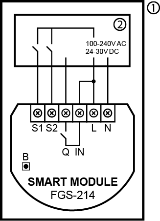
Diagram 1: Example connection of Smart Module
Notes for diagrams:
S1 -terminal for 1st button
S2 - terminal for 2nd button
Q - output terminal
IN - input terminal
L - terminal for live wire
N - terminal for neutral wire
B - maintenance button
1 - device/system housing
2 - electrical device
Inclusion/Exclusion
On factory default the device does not belong to any Z-Wave network. The device needs to be added to an existing wireless network to communicate with the devices of this network. This process is called Inclusion.
Devices can also be removed from a network. This process is called Exclusion. Both processes are initiated by the primary controller of the Z-Wave network. This controller is turned into exclusion respective inclusion mode. Inclusion and Exclusion is then performed doing a special manual action right on the device.
Inclusion
Quickly, three times click button connected to S1/S2 or the maintenance button.Exclusion
Quickly, three times click button connected to S1/S2 or the maintenance button.Product Usage
Z-Wave range test
The device has a built in Z-Wave network main controllers range tester.
Note: To make Z-Wave range test possible, the device must be added to the Z-Wave controller. Testing may stress the network, so it is recommended to perform the test only in special cases.
To test the main controllers range:
- Press and hold the maintenance button to enter the menu.
- Release button when the device glows magenta.
- Quickly click the button to confirm.
- Visual indicator will indicate the Z-Wave networks range (range signaling modes described below).
- To exit Z-Wave range test, press the button briefly.
Z-Wave range tester signaling modes:
- Visual indicator pulsing green - the device attempts to establish direct communication with the main controller. If a direct communication attempt fails, the device will try to establish a routed communication, through other modules, which will be signaled by visual indicator pulsing yellow.
- Visual indicator glowing green - the device communicates with the main controller directly.
- Visual indicator pulsing yellow - the device tries to establish a routed communication with the main controller through other modules (repeaters).
- Visual indicator glowing yellow - the device communicates with the main controller through the other modules. After 2 seconds the device will retry to establish direct communication with the main controller, which will be signaled with visual indicator pulsing green.
- Visual indicator pulsing violet - the device does communicate at the maximum distance of the Z-Wave network. If the connection proves successful it will be confirmed with a yellow glow. Its not recommended to use the device at the range limit.
- Visual indicator glowing red - the device is not able to connect to the main controller directly or through another Z-Wave network device (repeater).
Visual indications
The built-in LED light shows the current device status.
After powering the device:
- Green - device added to a Z-Wave network (non-secure, S0, S2 non-authenticated),
- Magenta - device added to a Z-Wave network (Security S2 Authenticated),
- Red - device not added to a Z-Wave network.
Update:
- Blinking cyan - update in progress,
- Green - update successful,
- Red - update not successful.
Menu:
- Blinking green - entering the menu (added as non-secure, S0, S2 non-authenticated),
- Blinking magenta - entering the menu (added as Security S2 Authenticated),
- Blinking red - entering the menu (not added to a Z-Wave network),
- Magenta - test Z-Wave network range,
- Yellow - reset to factory defaults.
Menu
Menu allows them to perform Z-Wave network actions. In order to use the menu:
- Press and hold the maintenance button to enter the menu.
- LED will signal to add status for 3 seconds (see Visual indications), then turn off for another 3 seconds.
- Release the button when device signals desired position with color:
- MAGENTA - test Z-Wave network range
- YELLOW - reset to factory defaults
- Quickly click the button to confirm.
Central Szene
Switch connected to S1 terminal - Scene ID 1
Switch clicked once - Key Pressed 1 time
Switch clicked twice - Key Pressed 2 times
Switch clicked thrice* Key Pressed 3 times
Switch held** - Key Held Down
Switch released** - Key Released
Switch connected to S2 terminal - Scene ID 2
Switch clicked once - Key Pressed 1 time
Switch clicked twice - Key Pressed 2 times
Switch clicked thrice - Key Pressed 3 times
Switch held** - Key Held Down
Switch released** - Key Released
* Activating triple clicks will disallow removing using this input.
** Not available for toggle switches.
Quick trouble shooting
Here are a few hints for network installation if things dont work as expected.
- Make sure a device is in factory reset state before including. In doubt exclude before include.
- If inclusion still fails, check if both devices use the same frequency.
- Remove all dead devices from associations. Otherwise you will see severe delays.
- Never use sleeping battery devices without a central controller.
- Dont poll FLIRS devices.
- Make sure to have enough mains powered device to benefit from the meshing
Association - one device controls an other device
Z-Wave devices control other Z-Wave devices. The relationship between one device controlling another device is called association. In order to control a different device, the controlling device needs to maintain a list of devices that will receive controlling commands. These lists are called association groups and they are always related to certain events (e.g. button pressed, sensor triggers, ...). In case the event happens all devices stored in the respective association group will receive the same wireless command wireless command, typically a 'Basic Set' Command.
Association Groups:
| Group Number | Maximum Nodes | Description |
|---|---|---|
| 1 | 1 | Lifeline |
| 2 | 5 | Basic Set Input S1 |
Configuration Parameters
Z-Wave products are supposed to work out of the box after inclusion, however certain configuration can adapt the function better to user needs or unlock further enhanced features.
IMPORTANT: Controllers may only allow configuring signed values. In order to set values in the range 128 ... 255 the value sent in the application shall be the desired value minus 256. For example: To set a parameter to 200 it may be needed to set a value of 200 minus 256 = minus 56. In case of a two byte value the same logic applies: Values greater than 32768 may needed to be given as negative values too.
Parameter 1: Remember relays state
This parameter determines the state of relays after power supply failure (e.g. power outage). For auto OFF and flashing modes the parameter is not relevant and the relay will always remain switched off. Size: 1 Byte, Default Value: 1
| Setting | Description |
|---|---|
| 0 | Relays remain switched off after restoring power |
| 1 | Restore remembered state of relays after restoring power |
| 2 | Restore remembered state of relays after restoring power, but for toggle switches (parameter 20/21 set to 1) set the same state as the current state of the switches |
Parameter 20: S1 input - switch type
This parameter defines as what type the device should treat the switch connected to the S1 terminal. Size: 1 Byte, Default Value: 0
| Setting | Description |
|---|---|
| 0 | Momentary switch |
| 1 | Toggle switch synchronized (contact closed - ON, contact opened - OFF) |
| 2 | Toggle switch with memory (device changes status when switch changes status) |
Parameter 21: S2 input - switch type
This parameter defines as what type the device should treat the switch connected to the S2 terminal. Size: 1 Byte, Default Value: 0
| Setting | Description |
|---|---|
| 0 | Momentary switch |
| 1 | Toggle switch synchronized (contact closed - ON, contact opened - OFF) |
| 2 | Toggle switch with memory (device changes status when switch changes status) |
Parameter 24: Inputs orientation
This parameter allows reversing operation of S1 and S2 inputs without changing the wiring. Use in case of incorrect wiring. Size: 1 Byte, Default Value: 0
| Setting | Description |
|---|---|
| 0 | Default (S1 - 1st channel, S2 - 2nd channel) |
| 1 | Reversed (S1 - 2nd channel, S2 - 1st channel) |
Parameter 30: Alarm configuration - 1st slot
This parameter determines to which alarm frames and how the device should react. The parameters consist of 4 bytes, three most significant bytes are set according to the official Z-Wave protocol specification. For a setting of this parameter, please refer to the manufacturers manual. Size: 4 Byte, Default Value: 0
| Setting | Description |
|---|
Parameter 31: Alarm configuration - 2nd slot (Water)
This parameter determines to which alarm frames and how the device should react. The parameters consist of 4 bytes, three most significant bytes are set according to the official Z-Wave protocol specification. For a setting of this parameter, please refer to the manufacturers manual. Size: 4 Byte, Default Value:
| Setting | Description |
|---|
Parameter 32: Alarm configuration - 3rd slot (Smoke)
This parameter determines to which alarm frames and how the device should react. The parameters consist of 4 bytes, three most significant bytes are set according to the official Z-Wave protocol specification. For a setting of this parameter, please refer to the manufacturers manual. Size: 4 Byte, Default Value:
| Setting | Description |
|---|
Parameter 33: Alarm configuration - 4th slot (CO)
This parameter determines to which alarm frames and how the device should react. The parameters consist of 4 bytes, three most significant bytes are set according to the official Z-Wave protocol specification.For a setting of this parameter, please refer to the manufacturers manual. For a setting of this parameter, please refer to the manufacturers manual. Size: 4 Byte, Default Value:
| Setting | Description |
|---|
Parameter 34: Alarm configuration - 5th slot (Heat)
This parameter determines to which alarm frames and how the device should react. The parameters consist of 4 bytes, three most significant bytes are set according to the official Z-Wave protocol specification. For a setting of this parameter, please refer to the manufacturers manual. Size: 4 Byte, Default Value:
| Setting | Description |
|---|
Parameter : Alarm configuration - duration
This parameter defines duration of alarm sequence. When time set in this parameter elapses, alarm is cancelled and relays restore normal operation, but do not recover state from before the alarm. Size: Byte, Default Value:
| Setting | Description |
|---|---|
| 0 | Infinite |
| 1 - 32400 | Seconds |
Parameter 40: S1 switch - scenes sent
This parameter determines which actions result in sending scene IDs assigned to them. Size: 1 Byte, Default Value: 0
| Setting | Description |
|---|---|
| 1 | Key pressed 1 time |
| 2 | Key pressed 2 times |
| 4 | Key pressed 3 times |
| 8 | Key hold down and key released |
| 15 | All |
Parameter 41: S2 switch - scenes sent
This parameter determines which actions result in sending scene IDs assigned to them. Size: 1 Byte, Default Value: 0
| Setting | Description |
|---|---|
| 1 | Key pressed 1 time |
| 2 | Key pressed 2 times |
| 4 | Key pressed 3 times |
| 8 | Key hold down and key released |
| 15 | All |
Parameter 150: First channel - operating mode
This parameter allows to choose operating mode for channel controlled with Q output. For timed modes (value 1, 2 or 3), time is set with parameter 154 and reaction to input change is set with parameter 152. Size: 1 Byte, Default Value: 0
| Setting | Description |
|---|---|
| 0 | Standard operation |
| 1 | Delayed OFF |
| 2 | Auto OFF |
| 3 | Flashing |
Parameter 152: First channel - reaction to input change in delayed/auto OFF modes
This parameter determines how the device reacts when changing state of S1 input in timed modes for first channel. Size: 1 Byte, Default Value: 0
| Setting | Description |
|---|---|
| 0 | Cancel mode and set default state |
| 1 | No reaction, mode runs until it ends |
| 2 | Reset timer, start counting time from the beginning |
Parameter 154: First channel - time parameter for delayed/auto OFF and flashing modes
This parameter allows to set time parameter used in timed modes for first channel. For delayed/auto OFF modes it determines duration, for flashing mode it determines cycle period. Size: 2 Byte, Default Value: 5
| Setting | Description |
|---|---|
| 0 | 0-0,1 seconds |
| 1 - 32000 | 0,1 - 3200 seconds |
Parameter 156: S1 input - Switch ON value sent to 2nd association group
This parameter defines value sent with Switch ON command to devices in 2nd association group when using S1 input. Size: 2 Byte, Default Value: 255
| Setting | Description |
|---|---|
| 0 | Turn off |
| 1 - 99 | Turn on and set level |
| 255 | Turn on with last level |
Parameter 157: S1 input - Switch OFF value sent to 2nd association group
This parameter defines value sent with Switch OFF command to devices in 2nd association group when using S1 input. Size: 2 Byte, Default Value: 0
| Setting | Description |
|---|---|
| 0 | Turn off |
| 1 - 99 | Turn on and set level |
| 255 | Turn on with last level |
Parameter 158: S1 input - Double Click value sent to 2nd association group
This parameter defines value sent with Double Click command to devices in 2nd association group when using S1 input. Size: 2 Byte, Default Value: 99
| Setting | Description |
|---|---|
| 0 | Turn off |
| 1 - 99 | Turn on and set level |
| 255 | Turn on with last level |
Parameter 162: Q output type
This parameter determines type of Q output. Size: 1 Byte, Default Value: 0
| Setting | Description |
|---|---|
| 0 | Normally Open (relay contacts opened turned off, closed when turned on) |
| 1 | Normally Closed (relay contacts closed turned off, opened when turned on) |
Technical Data
| Dimensions | 38 x 20 x 42 mm |
| Weight | 28 gr |
| Hardware Platform | ZM5101 |
| EAN | 5902701702083 |
| IP Class | IP 20 |
| Voltage | 230V |
| Load | 6,5A |
| Device Type | On/Off Power Switch |
| Generic Device Class | Binary Switch |
| Specific Device Class | Binary Power Switch |
| Firmware Version | 05.00 |
| Z-Wave Version | 06.04 |
| Z-Wave Product Id | 0x010f.0x0404.0x1000 |
| Frequency | Europe - 868,4 Mhz |
| Maximum transmission power | 5 mW |
Supported Command Classes
- Basic
- Application Status
- Switch Binary
- Transport Service
- Crc 16 Encap
- Association Grp Info
- Device Reset Locally
- Central Scene
- Zwaveplus Info
- Supervision
- Configuration
- Alarm
- Manufacturer Specific
- Powerlevel
- Protection
- Firmware Update Md
- Association
- Version
- Multi Channel Association
- Security
- Security 2
Explanation of Z-Wave specific terms
- Controller — is a Z-Wave device with capabilities to manage the network. Controllers are typically Gateways,Remote Controls or battery operated wall controllers.
- Slave — is a Z-Wave device without capabilities to manage the network. Slaves can be sensors, actuators and even remote controls.
- Primary Controller — is the central organizer of the network. It must be a controller. There can be only one primary controller in a Z-Wave network.
- Inclusion — is the process of adding new Z-Wave devices into a network.
- Exclusion — is the process of removing Z-Wave devices from the network.
- Association — is a control relationship between a controlling device and a controlled device.
- Wakeup Notification — is a special wireless message issued by a Z-Wave device to announces that is able to communicate.
- Node Information Frame — is a special wireless message issued by a Z-Wave device to announce its capabilities and functions.