Quickstart
This is a
On/Off Power Switch
for
Europe.
To run this device please connect it to your mains power supply.
To add this device to your network execute the following action:
- Quickly, three times press switch no. 1 or the B-button
Important safety information
Please read this manual carefully. Failure to follow the recommendations in this manual may be dangerous or may violate the law.
The manufacturer, importer, distributor and seller shall not be liable for any loss or damage resulting from failure to comply with the instructions in this manual or any other material.
Use this equipment only for its intended purpose. Follow the disposal instructions.
Do not dispose of electronic equipment or batteries in a fire or near open heat sources.
What is Z-Wave?
Z-Wave is the international wireless protocol for communication in the Smart Home. This
device is suited for use in the region mentioned in the Quickstart section.

Z-Wave ensures a reliable communication by reconfirming every message (two-way
communication) and every mains powered node can act as a repeater for other nodes
(meshed network) in case the receiver is not in direct wireless range of the
transmitter.
This device and every other certified Z-Wave device can be used together with any other
certified Z-Wave device regardless of brand and origin as long as both are suited for the
same frequency range.
If a device supports secure communication it will communicate with other devices
secure as long as this device provides the same or a higher level of security.
Otherwise it will automatically turn into a lower level of security to maintain
backward compatibility.
For more information about Z-Wave technology, devices, white papers etc. please refer
to www.z-wave.info.
Product Description
The In-Wall Double Relay Switch is hereinafter referred to as Fibaro Switch. It is designed to switch on/off devices connected to its terminals using radio waves, controllers and push button directly connected to Fibaro Switch.
The remotely controlled Double Relay Switch of FIBARO system is designed to operate in a wall switch box, wall socket box or in locations where the control of any two electric devices (up to 1.5kW each) is needed. It is also possible to send a signal to any system that is to be integrated with FIBARO system.
Prepare for Installation / Reset
Please read the user manual before installing the product.
In order to include (add) a Z-Wave device to a network it must be in factory default
state. Please make sure to reset the device into factory default. You can do this by
performing an Exclusion operation as described below in the manual. Every Z-Wave
controller is able to perform this operation however it is recommended to use the primary
controller of the previous network to make sure the very device is excluded properly
from this network.
Reset to factory default
This device also allows to be reset without any involvement of a Z-Wave controller. This
procedure should only be used when the primary controller is inoperable.
- Disconnect the power supply
- Remove the device from the wall switch box
- Connect the power supply
- Locate the B-button on the housing
- Press and hold the B-button for 3 seconds
- After few seconds the device will be reset
Safety Warning for Mains Powered Devices
ATTENTION: only authorized technicians under consideration of the country-specific
installation guidelines/norms may do works with mains power. Prior to the assembly of
the product, the voltage network has to be switched off and ensured against re-switching.
Installation
Connecting the device in a manner inconsistent with manual may cause risk to health, life or material damage.
When connecting the device act in accordance with the following rules:
- Connect only in accordance with one of the diagrams
- Electrical installation must be protected by overcurrent protection (fuse) of with a value not higher than 10A
- The device should be installed in a wall switch box compliant with a relevant national safety standards and with depth no less than 60mm
- Electrical switches used in installation should be compliant with the relevant safety standards
- Length of wires used to connect the control switch should not exceed 20m
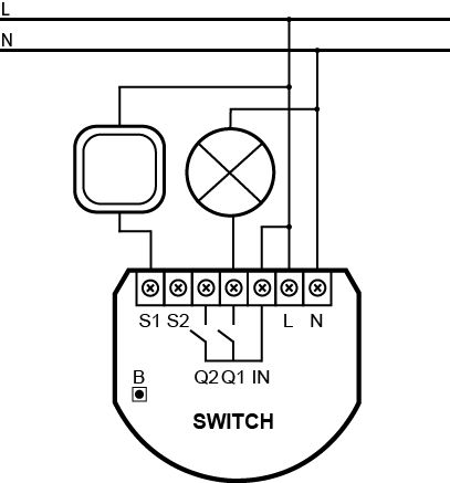
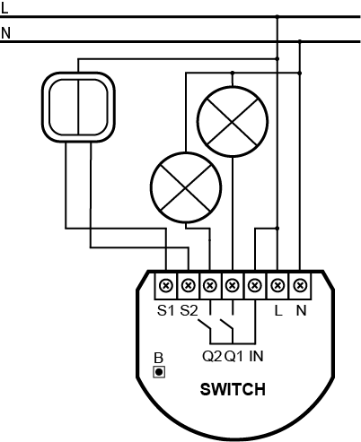
Notes for the diagrams:
S1 – terminal for switch no. 1 (has the option of entering the device in learning mode)
S2 – terminal for switch no. 2
IN – input terminal for load power supply
Q1 – output terminal of the device (controlling first connected load)
Q2 – output terminal of the device (controlling second connected load)
L – terminal for live lead
N – terminal for neutral lead
B – service button (used to add/remove the device)
Installation of the device:
- Switch off the mains voltage (disable the fuse)
- Open the wall switch box
- Connect with one of the diagrams below
- Verify correctness of connection
- Arrange the device and its antenna in a wall switch box
- Close the wall switch box
- Turn on the mains voltage
- Add the device to the Z-Wave network
Switch connected to the S1 terminal is a master switch. It starts the learning mode (Add/Remove). The switch connected to the S1 terminal will switch load connected to the Q1 terminal and switch connected to the S2 terminal will switch load connected to the Q2 terminal. Functionality of the switches can be reversed by adjusting advanced parameter.
Wiring diagrams:
Arranging the antenna
- Locate the antenna as far from metal elements as possible (connecting wires, bracket rings, etc.) in order to prevent interferences.
- Metal surfaces in the direct vicinity of the antenna (e.g. flush mounted metal boxes, metal door frames) may impair signal reception!
- Do not cut or shorten the antenna – its length is perfectly matched to the band in which the system operates.
Inclusion/Exclusion
On factory default the device does not belong to any Z-Wave network. The device needs
to be added to an existing wireless network to communicate with the devices of this network.
This process is called Inclusion.
Devices can also be removed from a network. This process is called Exclusion.
Both processes are initiated by the primary controller of the Z-Wave network. This
controller is turned into exclusion respective inclusion mode. Inclusion and Exclusion is
then performed doing a special manual action right on the device.
Inclusion
- Quickly, three times press switch no. 1 or the B-button
Exclusion
- Quickly, three times press switch no. 1 or the B-button
Product Usage
Controlling using an external switch
Momentary switch (after releasing the switch a spring automatically pushes back and disconnects the switch):
- Turn the load ON/OFF: briefly press the button corresponding to the chosen load
Toggle switch (operates as a two-position switch, it has no spring that would set one position of the switch):
- Turn the load ON/OFF: change the position of the button corresponding to the chosen load
ALL ON/ALL OFF
The device responds to commands ALL ON/ALL OFF that may be sent by the Z-Wave controller. ALL ON/ALL OFF commands are usually implemented in the remote controllers using Z-wave protocol, and they are used to issue commands directed to the entire system.
By default, both commands ALL ON and ALL OFF are accepted. Settings may be changed by modifying the value of parameter 1. In this way the user may determine to which commands the device should respond.
Quick trouble shooting
Here are a few hints for network installation if things dont work as expected.
- Make sure a device is in factory reset state before including. In doubt exclude before include.
- If inclusion still fails, check if both devices use the same frequency.
- Remove all dead devices from associations. Otherwise you will see severe delays.
- Never use sleeping battery devices without a central controller.
- Dont poll FLIRS devices.
- Make sure to have enough mains powered device to benefit from the meshing
Association - one device controls an other device
Z-Wave devices control other Z-Wave devices. The relationship between one device
controlling another device is called association. In order to control a different
device, the controlling device needs to maintain a list of devices that will receive
controlling commands. These lists are called association groups and they are always
related to certain events (e.g. button pressed, sensor triggers, ...). In case
the event happens all devices stored in the respective association group will
receive the same wireless command wireless command, typically a 'Basic Set' Command.
Association Groups:
| Group Number |
Maximum Nodes |
Description |
| 1 |
5 |
is assigned to S1 terminal – sending command frames to the associated devices whenever button connected to S1 terminal is pressed. |
| 2 |
5 |
is assigned to S2 terminal – sending command frames to the associated devices whenever button connected to S2 terminal is pressed. |
| 3 |
1 |
Lifeline reports the device status and allows to assign single device only (the main controller by default). |
Configuration Parameters
Z-Wave products are supposed to work out of the box after inclusion, however
certain configuration can adapt the function better to user needs or unlock further
enhanced features.
IMPORTANT: Controllers may only allow configuring
signed values. In order to set values in the range 128 ... 255 the value sent in
the application shall be the desired value minus 256. For example: To set a
parameter to 200 it may be needed to set a value of 200 minus 256 = minus 56.
In case of a two byte value the same logic applies: Values greater than 32768 may
needed to be given as negative values too.
Parameter 1: Switch all function
Allows to activate/deactivate ALL ON / ALL OFF functions.
Size: 1 Byte, Default Value: 255
| Setting |
Description |
| 0 |
ALL ON is not active, ALL OFF is not active |
| 1 |
ALL ON is not active, ALL OFF is active |
| 2 |
ALL ON is active, ALL OFF is not active |
| 255 |
ALL ON is active, ALL OFF is active |
Parameter 3: Override auto off
Auto off relay after specified time, with the possibility of manual override – immediate Off after button push.
Size: 1 Byte, Default Value: 0
| Setting |
Description |
| 0 |
manual override disabled. After single button push the relay turns on and automatically turns off after specified time. |
| 1 |
manual override enabled. After single button push the relay turns on and automatically turns off after specified time. Another button push turns the relay off immediately. |
Parameter 4: Auto off for relay 1
Relay will turn off automatically after time specified in this parameter.
Size: 2 Byte, Default Value: 0
| Setting |
Description |
| 0 |
auto off disabled |
| 1 - 65535 |
(0.1-6553.5s, 0.1 step) |
Parameter 5: Auto off for relay 2
Relay will turn off automatically after time specified in this parameter.
Size: 2 Byte, Default Value: 0
| Setting |
Description |
| 0 |
auto off disabled |
| 1 |
(0.1-6553.5s, 0.1 step) |
Parameter 6: Command frames sent to 1st association group
Size: 1 Byte, Default Value: 0
| Setting |
Description |
| 0 |
commands are sent when the device is turned on and off |
| 1 |
commands are sent when the device is turned off. Turning on the device does not send control commands. Double-clicking button sends ‘turn on’ command, dimmers memorize the last saved level. |
| 2 |
commands are sent when the device is turned off. Turning on the device does not send control commands. Double-clicking button sends ‘turn on’ command and dimmers are set to 100% brightness. |
Parameter 7: Command frames sent to 2nd association group
Size: 1 Byte, Default Value: 0
| Setting |
Description |
| 0 |
commands are sent when the device is turned on and off |
| 1 |
commands are sent when the device is turned off. Turning on the device does not send control commands. Double-clicking button sends ‘turn on’ command, dimmers memorize the last saved level. |
| 2 |
commands are sent when the device is turned off. Turning on the device does not send control commands. Double-clicking button sends ‘turn on’ command and dimmers are set to 100% brightness. |
Parameter 13: Switch and device status relation
Assigns status of the toggle (bistable) switch to status of the device.
Size: 1 Byte, Default Value: 0
| Setting |
Description |
| 0 |
turn on/off the device on switch status change |
| 1 |
device status depends on switch status (the device is ON when switch is ON and vice versa) |
Parameter 14: Switch type
Parameter defines type of connected switch
Size: 1 Byte, Default Value: 1
| Setting |
Description |
| 0 |
momentary switch |
| 1 |
toggle switch |
Parameter 15: Dim/shut command sent to 1st association group
Enabling this option allows the user to dim lighting/shut roller by associating Dimmer/Roller Shutter Controller. Hold button to change level or double press to set level to max (only momentary switch).
Size: 1 Byte, Default Value: 0
| Setting |
Description |
| 0 |
Dimmer/Roller Shutter Controller control is not active |
| 1 |
Dimmer/Roller Shutter Controller control is active |
Parameter 16: Restoring state after power failure
The device can save its state from before a power failure and restore it after power is back.
Size: 1 Byte, Default Value: 1
| Setting |
Description |
| 1 |
does not save the state after a power failure, it returns to “off” position |
| 1 |
restores state from before a power failure |
Parameter 30: General Alarm for relay 1
Response to General Alarm command frame.
Size: 1 Byte, Default Value: 3
| Setting |
Description |
| 0 |
DEACTIVATION – the device does not respond to alarm data frame |
| 1 |
ALARM RELAY ON – the device turns on after detecting an alarm |
| 2 |
ALARM RELAY OFF – the device turns off after detecting an alarm |
| 3 |
ALARM FLASHING – the device periodically changes its status to the opposite, when it detects an alarm within 10 min. |
Parameter 31: Flood Alarm for relay 1
Response to Flood Alarm command frame.
Size: 1 Byte, Default Value: 2
| Setting |
Description |
| 0 |
DEACTIVATION – the device does not respond to alarm data frames |
| 1 |
ALARM RELAY ON – the device turns on after detecting an alarm |
| 2 |
ALARM RELAY OFF – the device turns off after detecting an alarm |
| 3 |
ALARM FLASHING – the device periodically changes its status to the opposite, when it detects an alarm within 10 min. |
Parameter 32: Smoke, CO and CO2 Alarm for relay 1
Response to Smoke, CO and CO2 Alarm command frames.
Size: 1 Byte, Default Value: 3
| Setting |
Description |
| 0 |
DEACTIVATION – the device does not respond to alarm data frames |
| 1 |
ALARM RELAY ON – the device turns on after detecting an alarm |
| 2 |
ALARM RELAY OFF – the device turns off after detecting an alarm |
| 3 |
ALARM FLASHING – the device periodically changes its status to the opposite, when it detects an alarm within 10 min. |
Parameter 33: Temperature Alarm for relay 1
Response to Temperature Alarm command frame.
Size: 1 Byte, Default Value: 1
| Setting |
Description |
| 0 |
DEACTIVATION – the device does not respond to alarm data frames |
| 1 |
ALARM RELAY ON – the device turns on after detecting an alarm |
| 2 |
ALARM RELAY OFF – the device turns off after detecting an alarm |
| 3 |
ALARM FLASHING – the device periodically changes its status to the opposite, when it detects an alarm within 10 min. |
Parameter 39: Alarm flashing time
Determines how long the flashing will last in case of an alarm.
Size: 2 Byte, Default Value: 600
| Setting |
Description |
| 1 - 65535 |
time on seconds |
Parameter 40: General Alarm for relay 2
Response to General Alarm command frame.
Size: 3 Byte, Default Value: 1
| Setting |
Description |
| 0 |
DEACTIVATION – the device does not respond to alarm data frames |
| 1 |
ALARM RELAY ON – the device turns on after detecting an alarm |
| 2 |
ALARM RELAY OFF – the device turns off after detecting an alarm |
| 3 |
ALARM FLASHING – the device periodically changes its status to the opposite, when it detects an alarm within 10 min. |
Parameter : Flood Alarm for relay 2
Response to Flood Alarm command frame.
Size: 2 Byte, Default Value: 1
| Setting |
Description |
| 0 |
DEACTIVATION – the device does not respond to alarm data frames |
| 1 |
ALARM RELAY ON – the device turns on after detecting an alarm |
| 2 |
ALARM RELAY OFF – the device turns off after detecting an alarm |
| 3 |
ALARM FLASHING – the device periodically changes its status to the opposite, when it detects an alarm within 10 min. |
Parameter 42: Smoke, CO and CO2 Alarm for relay 2
Response to Smoke, CO and CO2 Alarm command frames.
Size: 1 Byte, Default Value: 3
| Setting |
Description |
| 0 |
DEACTIVATION – the device does not respond to alarm data frames |
| 1 |
ALARM RELAY ON – the device turns on after detecting an alarm |
| 2 |
ALARM RELAY OFF – the device turns off after detecting an alarm |
| 3 |
ALARM FLASHING – the device periodically changes its status to the opposite, when it detects an alarm within 10 min. |
Parameter 43: Temperature Alarm for relay 2
Response to Temperature Alarm command frame.
Size: 1 Byte, Default Value: 1
| Setting |
Description |
| 0 |
DEACTIVATION – the device does not respond to alarm data frames |
| 1 |
ALARM RELAY ON – the device turns on after detecting an alarm |
| 2 |
ALARM RELAY OFF – the device turns off after detecting an alarm |
| 3 |
ALARM FLASHING – the device periodically changes its status to the opposite, when it detects an alarm within 10 min. |
Technical Data
| Dimensions |
37x42x16 mm |
| Weight |
26 gr |
| Hardware Platform |
ZM3102 |
| EAN |
5902020528289 |
| IP Class |
IP 20 |
| Voltage |
230 V |
| Load |
2 x 1500W |
| Device Type |
On/Off Power Switch |
| Generic Device Class |
Binary Switch |
| Specific Device Class |
Binary Power Switch |
| Z-Wave Version |
4.52 |
| Certification ID |
ZC08-11070003 |
| Z-Wave Product Id |
0x010F.0x0200.0x0102 |
| Frequency |
Europe - 868,4 Mhz |
| Maximum transmission power |
5 mW |
Supported Command Classes
- Switch All
- Association
- Basic
- Configuration
- Manufacturer Specific
- Multi Channel
- Multi Channel Association
- Multi Channel V2
- No Operation
- Powerlevel
- Switch Binary
- Version
Controlled Command Classes
- Basic
- Multi Channel
- Multi Channel V2
- Switch Binary
Explanation of Z-Wave specific terms
- Controller — is a Z-Wave device with capabilities to manage the network.
Controllers are typically Gateways,Remote Controls or battery operated wall controllers.
- Slave — is a Z-Wave device without capabilities to manage the network.
Slaves can be sensors, actuators and even remote controls.
- Primary Controller — is the central organizer of the network. It must be
a controller. There can be only one primary controller in a Z-Wave network.
- Inclusion — is the process of adding new Z-Wave devices into a network.
- Exclusion — is the process of removing Z-Wave devices from the network.
- Association — is a control relationship between a controlling device and
a controlled device.
- Wakeup Notification — is a special wireless message issued by a Z-Wave
device to announces that is able to communicate.
- Node Information Frame — is a special wireless message issued by a
Z-Wave device to announce its capabilities and functions.