Fibaro
Walli Switch
SKU: FIBEFGWDSEU-221


Quickstart
This is a
1. Power the device.
2. Set the main controller in (Security/non-Security Mode) add mode (see the controllers manual).
3. Quickly, three times click one of the buttons.
4. If you are adding in Security S2 Authenticated, scan the DSK QR code or input the underlined part of the DSK (label on the bottom of the box).
5. LED will start blinking yellow, wait for the adding process to end.
6. Adding result will be confirmed by the Z-Wave controllers message and the LED frame:
To add the device to the Z-Wave network using SmartStart:
1. Set the main controller in Security S2 Authenticated add mode (see the controllers manual).
2. Scan the DSK QR code or input the underlined part of the DSK (label on the bottom of the box).
3. Power the device.
4. Wait for the adding process to start (up to few minutes), which is signaled with yellow LED blinking.
5. Adding result will be confirmed by the Z-Wave controllers message and the LED frame:
Important safety information
Please read this manual carefully. Failure to follow the recommendations in this manual may be dangerous or may violate the law. The manufacturer, importer, distributor and seller shall not be liable for any loss or damage resulting from failure to comply with the instructions in this manual or any other material. Use this equipment only for its intended purpose. Follow the disposal instructions. Do not dispose of electronic equipment or batteries in a fire or near open heat sources.What is Z-Wave?
Z-Wave is the international wireless protocol for communication in the Smart Home. This device is suited for use in the region mentioned in the Quickstart section.
Z-Wave ensures a reliable communication by reconfirming every message (two-way communication) and every mains powered node can act as a repeater for other nodes (meshed network) in case the receiver is not in direct wireless range of the transmitter.
This device and every other certified Z-Wave device can be used together with any other certified Z-Wave device regardless of brand and origin as long as both are suited for the same frequency range.
If a device supports secure communication it will communicate with other devices secure as long as this device provides the same or a higher level of security. Otherwise it will automatically turn into a lower level of security to maintain backward compatibility.
For more information about Z-Wave technology, devices, white papers etc. please refer to www.z-wave.info.
Product Description
FIBARO Walli Single Switch is a smart wall switch designed to control one or two light sources via Z-Wave network. It measures active power andenergy consumed by the controlledload. You can install it with provided cover plate or other compatible.
Prepare for Installation / Reset
Please read the user manual before installing the product.
In order to include (add) a Z-Wave device to a network it must be in factory default state. Please make sure to reset the device into factory default. You can do this by performing an Exclusion operation as described below in the manual. Every Z-Wave controller is able to perform this operation however it is recommended to use the primary controller of the previous network to make sure the very device is excluded properly from this network.
Reset to factory default
This device also allows to be reset without any involvement of a Z-Wave controller. This procedure should only be used when the primary controller is inoperable.
Resetting to factory defaults does not reset energy consumption memory.
1. Quickly, three times click, then press and hold one of the buttons to enter the menu.
2. Release the button when the device glows yellow.
3. Quickly click the button to confirm.
4. After a few seconds, the device will be restarted, which is signaled with the red LED color.
Safety Warning for Mains Powered Devices
ATTENTION: only authorized technicians under consideration of the country-specific installation guidelines/norms may do works with mains power. Prior to the assembly of the product, the voltage network has to be switched off and ensured against re-switching.
Installation
Notes for diagrams: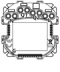
N - terminal for neutral wire
Q1 - output terminal of the 1st channel
Q2 - output terminal of the 2nd channel
L - terminal for live wire
G - groove used to measure wire length
Preparing for installation
Prepare wires by removing 11.5-13mm of insulation from their ends. You can use groove on the side of the unit to measure the length.
When installing with FIBARO or GIRA cover plates:
- Pull out the switch button.
- Take off the cover plate.
When installing with Legrand or Schneider cover plates:
- Pull out the original switch button.
- Take off the original cover plate.
- Dismount the original mounting frame.
- Snap the new mounting frame*.
* Additional mounting frames are sold separately.
Electrical connection
- Switch off the mains voltage (disable the fuse).
- Connect with one of the diagrams below:
- Verify correctness of connection.
- Tighten the terminal screws using PH1 screwdriver.
Connection for double switch configuration:
2-way Connection double switch configuration: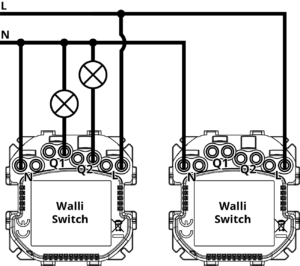
- Install 1st Walli Switch in box with load wires.
- Install 2nd Walli Switch in the second box (without the load)
- Add devices to the Home Center.
- Set association in 2nd Walli Switch to 1st Walli Switch in 2nd and 4th association group:
- Go to the device settings of 2nd Walli Switch by clicking the wrench icon,
- Go to Advanced tab, find Associations section and click Setting Association button,
- Find 2nd Association Group in Endpoint 0 and click it,
- Find 4th Association Group in Endpoint 0 and click it,
- Find 1st Walli Switch on the list and check it in the S column,
- Save.
- Repeat the previous step to set association in 1st Walli Switch to 2nd Walli Switch in 2nd and 4th association group.
- Group 1st Walli Switch (1st channel) with 2nd Walli Switch (1st channel) :
- Go to the device settings of 1st Walli Switch (1st channel) by clicking the wrench icon,
- Go to Advanced tab,
- In Device grouping section click 2nd Walli Switch (1st channel),
- Save.
- Repeat the previous step to group 1st Walli Switch (2nd channel) with 2nd Walli Switch (2nd channel).
Connection for singe switch configuration:
2-way Connection singe switch configuration: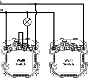
- Install 1st Walli Switch in box with load wires.
- Install 2nd Walli Switch in the second box (without the load)
- Change operating mode of both Walli Switches to Single Switch Mode:
- Quickly, three times click, then press and hold one of the buttons to enter the menu.
- Release button when the device glows white, then click again to confirm.
- Ring should blink white once.
- Add devices to the Home Center.
- Set association in 2nd Walli Switch to 1st Walli Switch in 2nd association group:
- Go to the device settings of 2nd Walli Switch by clicking the wrench icon,
- Go to Advanced tab, find Associations section and click Setting Association button,
- Find 2nd Association Group in Endpoint 0 and click it,
- Find 1st Walli Switch on the list and check it in the S column,
- Save.
- Repeat the previous step to set association in 1st Walli Switch to 2nd Walli Switch in 2nd association group.
- Group 1st Walli Switch with 2nd Walli Switch:
- Go to the device settings of 1st Walli Switch by clicking the wrench icon,
- Go to Advanced tab,
- In Device grouping section click 2nd Walli Switch,
- Save.
3-way switch installation:
If you install more Walli Switches, you need to make associations between each of them (just as in point no. 5).
Assembling the device
When installing the device in the mounting box orient the device with terminal screws going up or to the left (for horizontal button position) to ensure button order.
The light effect might look different for covers other than FIBARO Walli. You can adjust color and/or intensity of the LEDs to suit the particular cover (using parameters 11, 12, and 13) or disable it by changing parameter 13 to 0.
Fibaro Cover: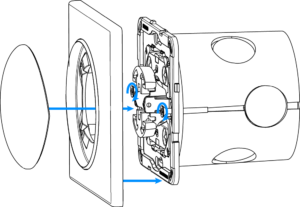
- Insert the device with mounting frame into the mounting box and secure with mounting claws and screws.
- Snap the cover plate to the device.
- Snap the switch button to the device.

- Insert the device with mounting frame into the mounting box and secure with mounting claws and screws.
- Snap the new cover plate to the device.
- Snap the switch button adapter* to the device.
- Snap the new switch button to the device.
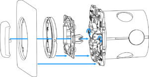
- Insert the device with mounting frame* into the mounting box and secure with mounting claws and screws.
- Snap the switch button adapter* to the device.
- Snap the new inner cover plate to the device.
- Snap the new outer cover plate to the device.
- Snap the new switch button to the device.
Schneider Cover:
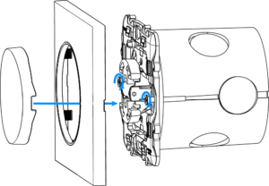
- Insert the device with mounting frame* into the mounting box and secure with mounting claws and screws.
- Snap the new cover plate to the device.
- Snap the new switch button to the device
Parts compatibility
An overview can be found in the manufacturers manual: https://manuals.fibaro.com/walli-switch/
Inclusion/Exclusion
On factory default the device does not belong to any Z-Wave network. The device needs to be added to an existing wireless network to communicate with the devices of this network. This process is called Inclusion.
Devices can also be removed from a network. This process is called Exclusion. Both processes are initiated by the primary controller of the Z-Wave network. This controller is turned into exclusion respective inclusion mode. Inclusion and Exclusion is then performed doing a special manual action right on the device.
Inclusion
Quickly, three times click one of the buttonsExclusion
Quickly, three times click one of the buttons.Product Usage
Compatible load types
- incandescent bulbs
- fluorescent lamps
- electronic transformers
- ferromagnetic transformers
- LED
Controls
1. First button
2. Second Button
3. LED Ring
Button control
Controlling connected loads
Perform following actions on one of the buttons to change state of the connected load. Button operation is configurable using parameters 20 and 24.
Double Switch mode - the 1st button controls the 1st channel and the 2nd button controls the 2nd channel:
- Click - change to the opposite state, ON/OFF (by default).
Single Switch mode - both buttons control the load:
- Click - change to the opposite state, ON/OFF (by default).
Other actions
Perform following actions on one of the buttons to:
- 3x Click - start learn mode to add/remove to/from Z-Wave network,
- 1,2,3x Click/hold/release - activate scene in the controller for specific action (requires configuration using parameters 40 and 41),
- 3x Click then press and hold - enter the menu.
he built-in LED light shows current device status.
After powering the device:
- Green - device added to a Z-Wave network (non-secure, S0, S2 non-authenticated),
- Magenta - device added to a Z-Wave network (Security S2 Authenticated),
- Red - device not added to a Z-Wave network.
State of the device:
- White - load turned ON (configurable using parameters 11 and 12).
Update:
- Blinking cyan - update in progress,
- Green - update successful,
- Red - update not successful.
Menu:
- Blinking green - entering the menu (added as non-secure, S0, S2 non-authenticated),
- Blinking magenta - entering the menu (added as Security S2 Authenticated),
- Blinking red - entering the menu (not added to a Z-Wave network),
- White - change or check operating mode (single or double switch),
- Green - reset energy consumption memory,
- Yellow - reset to factory defaults.
Single/Double Switch operating mode
The device can work as single or double switch:
- Double Switch mode (default) - the device can control two separate loads, but they can be up to 13A per channel and 16A total.
- Single Switch mode - the device can control only one load, but it can be rated up to 16A.
To change operating mode before adding to Z-Wave network:
- Quickly, three times click, then press and hold one of the buttons to enter the menu.
- Release button when the device glows white.
- Quickly click the button to confirm.
- The device will change and signal the new operating mode:
- 1 white blink - Single Switch mode,
- 2 white blinks - Double Switch mode.
To check operating mode after adding to Z-Wave network:
- Quickly, three times click, then press and hold one of the buttons to enter the menu.
- Release button when the device glows white.
- Quickly click the button to confirm.
- The device will signal the operating mode:
- 1 white blink - Single Switch mode,
- 2 white blinks - Double Switch mode.
Menu allows to perform Z-Wave network actions. In order to use the menu:
- Quickly, three times click, then press and hold one of the buttons to enter the menu, device blinks to signal adding status (see:
Visual indications). - Release the button when device signals desired position with colour:
- WHITE - change or check single/double switch mode
- GREEN - reset energy consumption memory
- MAGENTA - start Z-Wave range test
- YELLOW - reset to factory defaults
- Quickly click the button to confirm.
Communication to a Sleeping device (Wakeup)
This device is battery operated and turned into deep sleep state most of the time to save battery life time. Communication with the device is limited. In order to communicate with the device, a static controller C is needed in the network. This controller will maintain a mailbox for the battery operated devices and store commands that can not be received during deep sleep state. Without such a controller, communication may become impossible and/or the battery life time is significantly decreased.
This device will wakeup regularly and announce the wakeup state by sending out a so called Wakeup Notification. The controller can then empty the mailbox. Therefore, the device needs to be configured with the desired wakeup interval and the node ID of the controller. If the device was included by a static controller this controller will usually perform all necessary configurations. The wakeup interval is a tradeoff between maximal battery life time and the desired responses of the device. To wakeup the device please perform the following action: FIBARO Walli Double Switch is powered using DC power supply unit so it is always awake.
Quick trouble shooting
Here are a few hints for network installation if things dont work as expected.
- Make sure a device is in factory reset state before including. In doubt exclude before include.
- If inclusion still fails, check if both devices use the same frequency.
- Remove all dead devices from associations. Otherwise you will see severe delays.
- Never use sleeping battery devices without a central controller.
- Dont poll FLIRS devices.
- Make sure to have enough mains powered device to benefit from the meshing
Association - one device controls an other device
Z-Wave devices control other Z-Wave devices. The relationship between one device controlling another device is called association. In order to control a different device, the controlling device needs to maintain a list of devices that will receive controlling commands. These lists are called association groups and they are always related to certain events (e.g. button pressed, sensor triggers, ...). In case the event happens all devices stored in the respective association group will receive the same wireless command wireless command, typically a 'Basic Set' Command.
Association Groups:
| Group Number | Maximum Nodes | Description |
|---|---|---|
| 1 | 1 | Lifeline reports the device status and allowsfor assigning single device only (main controller by default). |
| 2 | 5 | On/Off (1) is used to turn the associated devices on/off reflecting button operation for 1st channel (uses Basic command class). |
| 3 | 5 | Dimmer (1) is used to change level of associated devices reflecting button operation for 1st channel (uses Switch Multilevel command class). |
| 4 | 5 | On/Off (2) is used to turn the associated devices on/off reflecting button operation for 2nd channel (uses Basic command class). |
| 5 | 5 | Dimmer (2) is used to change level of associated devices reflecting button operation for 2nd channel (uses Switch Multilevel command class). |
Configuration Parameters
Z-Wave products are supposed to work out of the box after inclusion, however certain configuration can adapt the function better to user needs or unlock further enhanced features.
IMPORTANT: Controllers may only allow configuring signed values. In order to set values in the range 128 ... 255 the value sent in the application shall be the desired value minus 256. For example: To set a parameter to 200 it may be needed to set a value of 200 minus 256 = minus 56. In case of a two byte value the same logic applies: Values greater than 32768 may needed to be given as negative values too.
Parameter 1: Remember device state
This parameter determines how the device will react in the event of power supply failure (e.g. power outage).The parameter is not relevant for outputs set to pulse mode (parameter 150/151 set to 2). Size: 1 Byte, Default Value: 1
| Setting | Description |
|---|---|
| 0 | remains switched off after restoring power |
| 1 | restores remembered state after restoring power |
Parameter 2: First channeloverload safety switch
This function allows to turn off the controlled device in case of exceeding the defined power.Controlled device can be turned back on via button or sending a control frame. Size: 4 Byte, Default Value: 0
| Setting | Description |
|---|---|
| 0 | function disabled |
| 10 - 36200 | (1.0-3620.0W, step 0.1W)power threshold |
Parameter 3: Second channeloverload safety switch
This function allows to turn off the controlled device in case of exceeding the defined power.Controlled device can be turned back on via button or sending a control frame. Size: 4 Byte, Default Value: 0
| Setting | Description |
|---|---|
| 0 | function disabled |
| 10 - 36200 | (1.0-3620.0W, step 0.1W)power threshold |
Parameter 10: LED framepower limit
This parameter determines maximum active power. Exceeding it results in the LED frameflashing violet. Function is active only when parameter 11 is set to 8 or 9. Size: 4 Byte, Default Value: 36800
| Setting | Description |
|---|---|
| 500 - 36800 | (50.0-3680.0W, step 0.1W)power threshold |
Parameter 11: LED framecolour when ON
This parameter defines the LED colour when thedevice is ON.When set to 8 or 9, LED frame colour will change depending on he measured power and parameter 10. Other colours are set permanently and do not depend on power consumption. Size: 1 Byte, Default Value: 1
| Setting | Description |
|---|---|
| 0 | LED disabled |
| 1 | White |
| 2 | Red |
| 3 | Green |
| 4 | Blue |
| 5 | Yellow |
| 6 | Cyan |
| 7 | Magenta |
| 8 | colour changes smoothly depending on measured power |
| 9 | colour changes in steps depending on measured power |
Parameter 12: LED framecolour when OFF
This parameter defines the LED colour when the device is OFF. Size: 1 Byte, Default Value: 0
| Setting | Description |
|---|---|
| 0 | LED disabled |
| 1 | White |
| 2 | Red |
| 3 | Green |
| 4 | Blue |
| 5 | Yellow |
| 6 | Cyan |
| 7 | Magenta |
Parameter 13: LED framebrightness
This parameter allows to adjust the LED frame brightness. Size: 1 Byte, Default Value: 100
| Setting | Description |
|---|---|
| 0 | LED disabled |
| 1 - 100 | (1-100% brightness) |
| 101 | brightness directly proportional to measured power |
| 102 | brightness inversely proportional to measured power |
Parameter 20: Buttons operation
This parameter defines how device buttons should control the channels. Size: 1 Byte, Default Value: 1
| Setting | Description |
|---|---|
| 1 | 1st and 2nd button toggle the load |
| 2 | 1st button turns the load ON, 2nd button turns the load OFF |
Parameter 24: Buttons orientation
This parameter allows reversing the operation of the buttons. Size: 1 Byte, Default Value: 0
| Setting | Description |
|---|---|
| 0 | default (1st button controls 1st channel, 2nd button controls 2nd channel) |
| 1 | reversed (1st button controls 2nd channel, 2nd button controls 1st channel) |
Parameter 25: Outputs orientation
This parameter allows reversing the operation of Q1 and Q2 without changing the wiring (e.g. in case of invalid connection). Changing orientation turns both outputs off. Size: 1 Byte, Default Value: 0
| Setting | Description |
|---|---|
| 0 | default (Q1 - 1st channel, Q2 - 2nd channel) |
| 1 | reversed (Q1 - 2nd channel, Q2 - 1st channel) |
Parameter 30: Alarm configuration - 1st slot
This parameter determines to which alarm frames and how the device should react. The parameters consist of 4 bytes, three most significant bytes are set according to the official Z-Wave protocol specification. Size: 4 Byte, Default Value: 0
| Setting | Description |
|---|---|
| 1 - 0 | [MSB]Notification Type |
| 2 | Notification Value |
| 3 | Event/State Parameters |
| 4 | [LSB]action |
Parameter 31: Alarm configuration - 2nd slot
This parameter determines to which alarm frames and how the device should react. The parameters consist of 4 bytes, three most significant bytes are set according to the official Z-Wave protocol specification. Size: 4 Byte, Default Value: 0
| Setting | Description |
|---|---|
| 1 | [MSB]Notification Type |
| 2 | Notification Value |
| 3 | Event/State Parameters |
| 4 | [LSB]action |
Parameter 32: Alarm configuration - 3rd slot
This parameter determines to which alarm frames and how the device should react. The parameters consist of 4 bytes, three most significant bytes are set according to the official Z-Wave protocol specification. Size: 4 Byte, Default Value: 0
| Setting | Description |
|---|---|
| 1 | [MSB]Notification Type |
| 2 | Notification Value |
| 3 | Event/State Parameters |
| 4 | [LSB]action |
Parameter 33: Alarm configuration - 4th slot
This parameter determines to which alarm frames and how the device should react. The parameters consist of 4 bytes, three most significant bytes are set according to the official Z-Wave protocol specification. Size: 4 Byte, Default Value: 0
| Setting | Description |
|---|---|
| 0 | Notification Type |
| 1 | [MSB]Notification Type |
| 2 | Notification Status |
| 3 | Event/State Parameters |
| 4 | [LSB]action |
Parameter 34: Alarm configuration - 5th slot
This parameter determines to which alarm frames and how the device should react. Theparameters consist of 4 bytes, three most significant bytes are set according to the officialZ-Wave protocol specification. Size: 4 Byte, Default Value: 0
| Setting | Description |
|---|---|
| 1 | [MSB]Notification Type |
| 2 | Notification Status |
| 3 | Event/State Parameters |
| 4 | [LSB] - action |
Parameter 35: Alarm configurationduration
This parameter defines duration of alarm sequence.When time set in this parameter elapses, alarm is cancelled, LED frame and relay restore normal operation, but do not recover state from before the alarm. Size: 2 Byte, Default Value: 600
| Setting | Description |
|---|---|
| 0 | infinite |
| 1 - 32400 | (1s-9h, 1s step)duration |
Parameter 40: First buttonscenes sent
This parameter determines which actions result in sending scene IDs assigned to them. Values can be combined (e.g. 1+2=3 means that scenes for single and double click are sent). Enabling scenes for triple click disables entering the device in learn mode by triple clicking. Size: 1 Byte, Default Value: 0
| Setting | Description |
|---|---|
| 1 | Key pressed 1 time |
| 2 | Key pressed 2 time |
| 4 | Key pressed 3 time |
| 8 | Key hold down and key released |
Parameter 41: Second buttonscenes sent
This parameter determines which actions result in sending scene IDs assigned to them. Values can be combined (e.g. 1+2=3 means that scenes for single and double click are sent). Enabling scenes for triple click disables entering the device in learn mode by triple clicking. Size: 1 Byte, Default Value: 0
| Setting | Description |
|---|---|
| 1 | Key pressed 1 time |
| 2 | Key pressed 2 time |
| 4 | Key pressed 3 time |
| 8 | Key hold down and key released |
Parameter 60: Power reportsinclude self-consumption
This parameter determines whether the power measurements should include power consumed by the device itself. Size: 1 Byte, Default Value: 0
| Setting | Description |
|---|---|
| 0 | Self-consumption not included |
| 1 | Self-consumption included |
Parameter 61: Power reports for first channelon change
This parameter defines minimal change (from the last reported) in measured power that results in sending new report. For loads under 50W the parameter is irrelevant, report are sent every 5W change. Size: 2 Byte, Default Value: 15
| Setting | Description |
|---|---|
| 0 | reporting on change disabled |
| 1 - 500 | (1-500%, 1% step)minimal change |
Parameter 62: Power reports for first channelperiodic
This parameter defines reporting interval for measured power. Periodic reports are independent from changes in value (parameter 61). Size: 2 Byte, Default Value: 3600
| Setting | Description |
|---|---|
| 0 | periodic reports disabled |
| 30 - 32400 | (30s-9h, 1s step)time interval |
Parameter 63: Power reports for second channelon change
This parameter defines minimal change (from the last reported) in measured power that results in sending new report. For loads under 50W the parameter is irrelevant, report are sent every 5W change. Size: 2 Byte, Default Value: 15
| Setting | Description |
|---|---|
| 0 | reporting on change disabled |
| 1 - 500 | (1-500%, 1% step)minimal change |
Parameter 64: Power reports for second channelperiodic
This parameter defines reporting interval for measured power. Periodic reports are independent from changes in value (parameter 63). Size: 2 Byte, Default Value: 3600
| Setting | Description |
|---|---|
| 0 | periodic reports disabled |
| 30 - 32400 | (30s-9h, 1s step)time interval |
Parameter 65: Energy reports for first channelon change
This parameter defines minimal change (from the last reported) in measured energy that results in sending new report. Size: 2 Byte, Default Value: 10
| Setting | Description |
|---|---|
| 0 | reporting on change disabled |
| 1 - 500 | (0.01-5kWh, 0.01kWh step)minimal change |
Parameter 66: Energy reports for first channelperiodic
This parameter defines reporting interval for measured energy.Periodic reports are independent from changes in value (parameter 66). Size: 2 Byte, Default Value: 3600
| Setting | Description |
|---|---|
| 0 | periodic reports disabled |
| 30 - 32400 | (30s-9h, 1s step)time interval |
Parameter 67: Energy reports for second channelon change
This parameter defines minimal change (from the last reported) in measured energy that results in sending new report. Size: 2 Byte, Default Value: 10
| Setting | Description |
|---|---|
| 0 | reporting on change disabled |
| 1 - 500 | (0.01-5kWh, 0.01kWh step)minimal change |
Parameter 68: Energy reports for second channelperiodic
This parameter defines reporting interval for measured energy. Periodic reports are independent from changes in value (parameter 67). Size: 2 Byte, Default Value: 3600
| Setting | Description |
|---|---|
| 0 | periodic reports disabled |
| 30 - 32400 | (30s-9h, 1s step)time interval |
Parameter 150: First channeloperating mode
This parameter allows to choose operating for the 1st channel . Size: 1 Byte, Default Value: 0
| Setting | Description |
|---|---|
| 0 | standard operation |
| 1 | delayed OFF |
| 2 | single pulse |
Parameter 151: Second channeloperating mode
This parameter allows to choose operating for the 2nd channel. Size: 1 Byte, Default Value: 0
| Setting | Description |
|---|---|
| 0 | standard operation |
| 1 | delayed OFF |
| 2 | single pulse |
Parameter 152: First channel - reaction to switch for delayed OFF / pulse modes
This parameter determines how the device in timed mode reacts to pushing the button for 1st channel.The parameter is relevant only for button toggles modes (parameter 20 set to 1 or 3). Size: 1 Byte, Default Value: 0
| Setting | Description |
|---|---|
| 0 | cancel mode and set default state |
| 1 | no reaction - mode runs until it ends |
| 2 | reset timer - start counting from the beginning |
Parameter 153: Second channel - reaction to switch for delayed OFF / pulse modes
This parameter determines how the device in timed mode reacts to pushing the button for 2nd channel.The parameter is relevant only for button toggles modes (parameter 20 set to 1 or 3). Size: 1 Byte, Default Value: 0
| Setting | Description |
|---|---|
| 0 | cancel mode and set default state |
| 1 | no reaction - mode runs until it ends |
| 2 | reset timer - start counting from the beginning |
Parameter 154: First channel - time parameter for delayed OFF / pulse modes
This parameter allows to set time parameter used in timed modes for 1st channel (parameter 150). Delay time for switching off or duration of the pulse. Size: 2 Byte, Default Value: 50
| Setting | Description |
|---|---|
| 0 | 0.1 second |
| 1 - 32000 | (1-32000s, 1s step)time parameter |
Parameter 155: Second channel - time parameter for delayed OFF / pulse modes
This parameter allows to set time parameter used in timed modes for 2nd channel (parameter 151). Delay time for switching off or duration of the pulse. Size: 2 Byte, Default Value: 50
| Setting | Description |
|---|---|
| 0 | 0.1 second |
| 1 - 32000 | (1-32000s, 1s step)time parameter |
Parameter 156: First channelSwitch ON value sent to 2nd and 3rd association groups
This parameter defines value sent with Switch ON command to devices associated in 2nd and 3rd association group for manual changes of Endpoint 1 state. Size: 2 Byte, Default Value: 255
| Setting | Description |
|---|---|
| 0 - 99 | 2nd association group |
| 255 | 3rd association group |
Parameter 157: First channelSwitch OFF value sent to 2nd and 3rd association groups
This parameter defines value sent with Switch OFF command to devices associated in 2nd and 3rd association group for manual changes of Endpoint 1 state. Size: 2 Byte, Default Value: 0
| Setting | Description |
|---|---|
| 0 - 99 | 2nd association group |
| 255 | 3rd association group |
Parameter 158: First channelDouble Click value sent to 2nd and 3rd association groups
This parameter defines value sent with Double Click command to devices associated in 2nd and 3rd association group for manual changes of Endpoint 1 state. Size: 2 Byte, Default Value: 99
| Setting | Description |
|---|---|
| 0 - 99 | 2nd association group |
| 255 | 3rd association group |
Parameter 159: Second channelSwitch ON value sent to 4th and 5th association groups
This parameter defines value sent with Switch ON command to devices associated in 4th and5th association group for manual changes of Endpoint 2 state. Size: 2 Byte, Default Value: 255
| Setting | Description |
|---|---|
| 0 - 99 | 4th association group |
| 255 | 5th association group |
Parameter 160: Second channelSwitch OFF value sent to 4th and 5th association groups
This parameter defines value sent with Switch OFF command to devices associated in 4th and 5th association group for manual changes of Endpoint 2 state. Size: 2 Byte, Default Value: 0
| Setting | Description |
|---|---|
| 0 - 99 | 4th association group |
| 255 | 5th association group |
Parameter 161: Second channelDouble Click value sent to 4th and 5th association groups
This parameter defines value sent with Double Click command to devices associated in 4th and 5th association group for manual changes of Endpoint 2 state. Size: 2 Byte, Default Value: 99
| Setting | Description |
|---|---|
| 0 - 99 | 4th association group |
| 255 | 5th association group |
Technical Data
| Dimensions | 86 x 86 x 52 mm |
| Weight | 110 gr |
| Hardware Platform | ZM5101 |
| EAN | 5902701701352 |
| IP Class | IP 20 |
| Voltage | 230V |
| Load | 13 A |
| Device Type | On/Off Power Switch |
| Network Operation | Always On Slave |
| Z-Wave Version | 6.81.01 |
| Certification ID | ZC10-19056499 |
| Z-Wave Product Id | 0x010F.0x1A01.0x1000 |
| Supported Meter Type | Electric Energy |
| Color | White |
| Electric Load Type | FluorescentIncandescentLED |
| Supported Notification Types | Power ManagementSystem |
| Loads Controlled | 4 |
| Switch Type | Push Button |
| Frequency | Europe - 868,4 Mhz |
| Maximum transmission power | 5 mW |
Supported Command Classes
- Application Status
- Association Grp Info V2
- Association V2
- Basic
- Central Scene V3
- Configuration
- Crc 16 Encap
- Device Reset Locally
- Firmware Update Md V4
- Manufacturer Specific V2
- Meter V3
- Multi Channel Association V3
- Multi Channel V4
- Notification V8
- Powerlevel
- Protection V2
- Security
- Security 2
- Supervision
- Switch Binary
- Transport Service V2
- Version V2
- Zwaveplus Info V2
Controlled Command Classes
- Basic
Explanation of Z-Wave specific terms
- Controller — is a Z-Wave device with capabilities to manage the network. Controllers are typically Gateways,Remote Controls or battery operated wall controllers.
- Slave — is a Z-Wave device without capabilities to manage the network. Slaves can be sensors, actuators and even remote controls.
- Primary Controller — is the central organizer of the network. It must be a controller. There can be only one primary controller in a Z-Wave network.
- Inclusion — is the process of adding new Z-Wave devices into a network.
- Exclusion — is the process of removing Z-Wave devices from the network.
- Association — is a control relationship between a controlling device and a controlled device.
- Wakeup Notification — is a special wireless message issued by a Z-Wave device to announces that is able to communicate.
- Node Information Frame — is a special wireless message issued by a Z-Wave device to announce its capabilities and functions.