Fibaro Group
Universal Binary Sensor
SKU: FIB_FGBS-001
Quickstart
This is a
Tripple Click the "B" Button on the device confirms the inclusion and exclusion.
Important safety information
Please read this manual carefully. Failure to follow the recommendations in this manual may be dangerous or may violate the law. The manufacturer, importer, distributor and seller shall not be liable for any loss or damage resulting from failure to comply with the instructions in this manual or any other material. Use this equipment only for its intended purpose. Follow the disposal instructions. Do not dispose of electronic equipment or batteries in a fire or near open heat sources.What is Z-Wave?
Z-Wave is the international wireless protocol for communication in the Smart Home. This device is suited for use in the region mentioned in the Quickstart section.
Z-Wave ensures a reliable communication by reconfirming every message (two-way communication) and every mains powered node can act as a repeater for other nodes (meshed network) in case the receiver is not in direct wireless range of the transmitter.
This device and every other certified Z-Wave device can be used together with any other certified Z-Wave device regardless of brand and origin as long as both are suited for the same frequency range.
If a device supports secure communication it will communicate with other devices secure as long as this device provides the same or a higher level of security. Otherwise it will automatically turn into a lower level of security to maintain backward compatibility.
For more information about Z-Wave technology, devices, white papers etc. please refer to www.z-wave.info.
Product Description
This universal Z-Wave sensor is designed to improve electronic devices with on/off switches or analog outputs by connecting them to a wireless Z-Wave network. The device can service two binary inputs and up to 4 DS18B20 temperature probes. The device can also control up to two external digital inputs (up to 150 mA). The sensor is designed to be included into the housing of another device and to be powered by this device with an input power between 9 and 30 V DC.
Prepare for Installation / Reset
Please read the user manual before installing the product.
In order to include (add) a Z-Wave device to a network it must be in factory default state. Please make sure to reset the device into factory default. You can do this by performing an Exclusion operation as described below in the manual. Every Z-Wave controller is able to perform this operation however it is recommended to use the primary controller of the previous network to make sure the very device is excluded properly from this network.
Reset to factory default
This device also allows to be reset without any involvement of a Z-Wave controller. This procedure should only be used when the primary controller is inoperable.
Disconnect and reconnect the device from the power supply while folding down the "B" button for 10 seconds. After the next reconnect of the power the device is back in factory default.
Safety Warning for Mains Powered Devices
ATTENTION: only authorized technicians under consideration of the country-specific installation guidelines/norms may do works with mains power. Prior to the assembly of the product, the voltage network has to be switched off and ensured against re-switching.
Installation
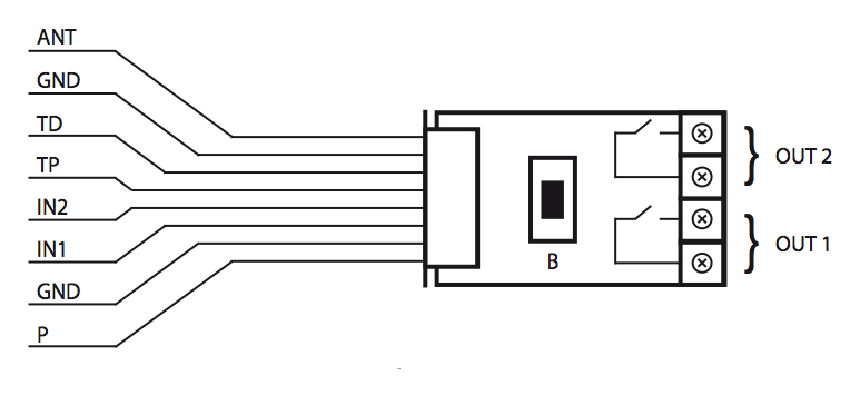
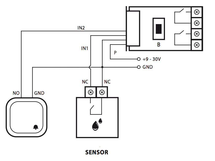
 Explanation of the cable markings
- P (POWER), power supply cable, red
- GND (Ground), ground cable, blue
- OUT1, output No 1, assigned to input IN1
- OUT2, output No 2, assigned to input IN2
- TP (TEMP_POWER), power supply cable to the DS18B20 temperature sensor, brown
- TD (TEMP_DATA), signal cable to the DS18B20 temperature sensors, white
- ANT, antenna, black
- OUT1, output no 1 - assigned to input IN1
- OUT2, output no 2 - assigned to input IN2
- B, maintenance button
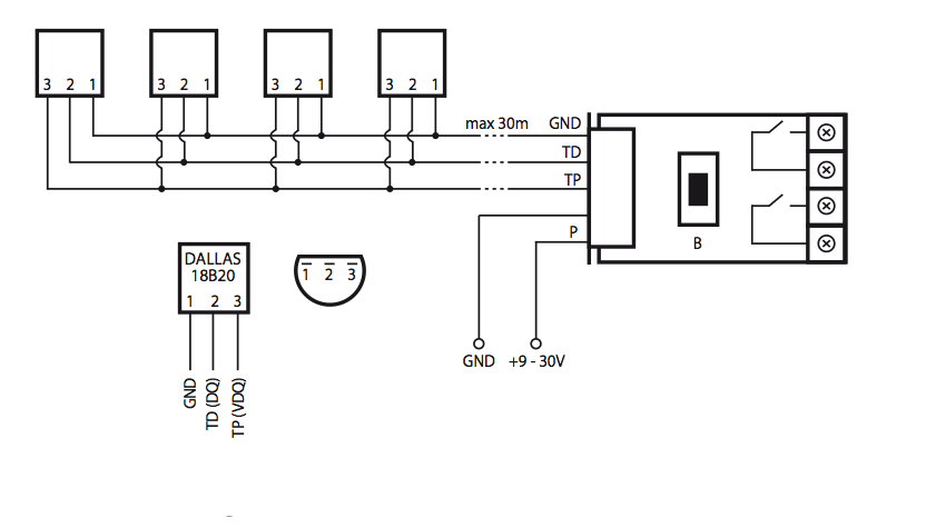
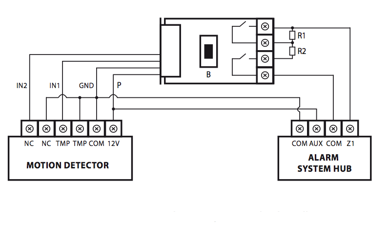
The external temperature sensors DS18B20 are connected to the device as shown on this picture. The subsequent image shows how to connect such an external switch or an external sensor to the terminals.
Inclusion/Exclusion
On factory default the device does not belong to any Z-Wave network. The device needs to be added to an existing wireless network to communicate with the devices of this network. This process is called Inclusion.
Devices can also be removed from a network. This process is called Exclusion. Both processes are initiated by the primary controller of the Z-Wave network. This controller is turned into exclusion respective inclusion mode. Inclusion and Exclusion is then performed doing a special manual action right on the device.
Inclusion
Tripple Click the "B" Button on the device confirms inclusion and exclusion.
Exclusion
Tripple Click the "B" Button on the device confirms inclusion and exclusion.
Node Information Frame
The Node Information Frame (NIF) is the business card of a Z-Wave device. It contains information about the device type and the technical capabilities. The inclusion and exclusion of the device is confirmed by sending out a Node Information Frame. Beside this it may be needed for certain network operations to send out a Node Information Frame. To issue a NIF execute the following action:
Tripple Click the
Quick trouble shooting
Here are a few hints for network installation if things dont work as expected.
- Make sure a device is in factory reset state before including. In doubt exclude before include.
- If inclusion still fails, check if both devices use the same frequency.
- Remove all dead devices from associations. Otherwise you will see severe delays.
- Never use sleeping battery devices without a central controller.
- Dont poll FLIRS devices.
- Make sure to have enough mains powered device to benefit from the meshing
Association - one device controls an other device
Z-Wave devices control other Z-Wave devices. The relationship between one device controlling another device is called association. In order to control a different device, the controlling device needs to maintain a list of devices that will receive controlling commands. These lists are called association groups and they are always related to certain events (e.g. button pressed, sensor triggers, ...). In case the event happens all devices stored in the respective association group will receive the same wireless command wireless command, typically a 'Basic Set' Command.
Association Groups:
| Group Number | Maximum Nodes | Description |
|---|---|---|
| 1 | 1 | Input IN1 |
| 2 | 5 | Input IN2 |
| 3 | 5 | reports device status |
Configuration Parameters
Z-Wave products are supposed to work out of the box after inclusion, however certain configuration can adapt the function better to user needs or unlock further enhanced features.
IMPORTANT: Controllers may only allow configuring signed values. In order to set values in the range 128 ... 255 the value sent in the application shall be the desired value minus 256. For example: To set a parameter to 200 it may be needed to set a value of 200 minus 256 = minus 56. In case of a two byte value the same logic applies: Values greater than 32768 may needed to be given as negative values too.
Parameter 1: Input 1 Alarm Delay
defines the delay from triggering Input 1 to sending an alarm. Removing Alarm condition will cancel alarm Size: 2 Byte, Default Value: 0
| Setting | Description |
|---|---|
| 1 - 65535 | seconds |
Parameter 2: Input 2 Alarm Delay
defines the delay from triggering Input 2 to sending an alarm. Removing Alarm condition will cancel alarm Size: 2 Byte, Default Value: 0
| Setting | Description |
|---|---|
| 1 - 65535 | seconds |
Parameter 3: Type of Input 1
Size: 1 Byte, Default Value: 1
| Setting | Description |
|---|---|
| 0 | INPUT_NO (Normal Open) |
| 1 | INPUT_NC (Normal Close) |
| 2 | INPUT_MONOSTABLE (Monostabil) |
| 3 | INPUT_BISTABLE (bistabil) |
Parameter 4: Type of Input 2
Size: 1 Byte, Default Value: 1
| Setting | Description |
|---|---|
| 0 | INPUT_NO (Normal Open) |
| 1 | INPUT_NC (Normal Close) |
| 2 | INPUT_MONOSTABLE (Monostabil) |
| 3 | INPUT_BISTABLE (bistabil) |
Parameter 5: Type of control frame activated via IN input 1
The parameter allows you to specify the type of an alarm frame for Input 1 Size: 1 Byte, Default Value: 255
| Setting | Description |
|---|---|
| 0 | ALARM GENERIC frame |
| 1 | ALARM SMOKE frame |
| 2 | ALARM CO frame |
| 3 | ALARM CO2 frame |
| 4 | ALARM HEAT frame |
| 5 | ALARM WATER frame |
| 255 | Control frame BASIC_SET |
Parameter 6: Type of control frame activated via IN input 2
The parameter allows you to specify the type of an alarm frame for Input 2 Size: 1 Byte, Default Value: 255
| Setting | Description |
|---|---|
| 0 | ALARM GENERIC frame |
| 1 | ALARM SMOKE frame |
| 2 | ALARM CO frame |
| 3 | ALARM CO2 frame |
| 4 | ALARM HEAT frame |
| 5 | ALARM WATER frame |
| 255 | Control frame BASIC_SET |
Parameter 7: Value of the parameter specifying the forced level of dimming/opening roller blinds from Input 1
In case of alarm frames an alarm priority is specified. Value of 255 makes it possible to activate a device. In case of the Dimmer module it means activating the device and setting it to the previously stored condition, e.g. when Dimmer is set to 30%, deactivated and then reactivated using 255 commend, it will be automatically set to the previous condition i.e. 30%. Size: 1 Byte, Default Value: 0
| Setting | Description |
|---|---|
| 1 - 99 | Dimming level |
| 255 | Turn On |
Parameter 8: Value of the parameter specifying the forced level of dimming/opening roller blinds from Input 2
In case of alarm frames an alarm priority is specified. Value of 255 makes it possible to activate a device. In case of the Dimmer module it means activating the device and setting it to the previously stored condition, e.g. when Dimmer is set to 30%, deactivated and then reactivated using 255 commend, it will be automatically set to the previous condition i.e. 30%. Size: 1 Byte, Default Value: 0
| Setting | Description |
|---|---|
| 1 - 99 | Dimming level |
| 255 | Turn On |
Parameter 9: Deactivating transmission of the alarm cancelling frame or the control frame deactivating the device (Basic)
It allows for disabling the function of deactivating the device and cancelling alarms for devices associated with IN input. Size: 1 Byte, Default Value: 0
| Setting | Description |
|---|---|
| 0 | information is sent to group 1 and 2 |
| 1 | information is not sent for group 2 but sent for group 1 |
| 2 | information is not sent for group 1 but sent for group 2 |
| 3 | information is not sent |
Parameter 10: Interval between successive readings of temperature from all sensors connected to the device.
Size: 1 Byte, Default Value: 200
| Setting | Description |
|---|---|
| 0 | disable |
| 1 - 255 | seconds |
Parameter 11: Sende Interval Temperaturwerte
Interval between forcing to send report concerning the temperature conditions. The forced report is sent immediately after the next reading of temperature from the sensor, irrespective of the settings of parameter no. 12. Frequent sending of temperature condition reports is reasonable when the sensor is located somewhere where can occure rapid changes of ambient temperature. In other cases it is recommended to leave the parameter set to the default value. Size: 1 Byte, Default Value: 20
| Setting | Description |
|---|---|
| 1 - 255 | seconds |
Parameter 12: Trigger level to send out temperature report
defines the maximum deviation of the actual temperature compared to the last wirelessly reported temperature to create a new wireless report to the device in association group 3. If set to zero a report will be generated at every regular wakeup of the device but as a minimum every 4 minutes. Size: 1 Byte, Default Value: 8
| Setting | Description |
|---|---|
| 0 | information about the temperature will be sent every time, immediately once the readings have been taken from the sensor |
| 1 - 255 | 0,0625°C - 16°C (step 0,0625°C) |
Parameter 13: Sending an alarm or control frame (for IN input, depending on parameter no.5 value), and TMP button alarm frame
The frame is sent in broadcast mode, i.e. to all devices within range - information sent in this mode is not repeated by the mesh network. Size: 1 Byte, Default Value: 0
| Setting | Description |
|---|---|
| 0 | IN1 and IN2 Broadcast mode inactive |
| 1 | IN1 broadcast mode active, IN2 broadcast mode inactive |
| 2 | IN1 broadcast mode inactive, IN2 broadcast mode active |
| 3 | IN1 and IN2 broadcast mode active |
Parameter 14: Scene activation functionality
IN input: Switch from (off to on) ID10; Switch from (on) to (off) ID11; Remaining IDs are recognized correctly if the value of parameter no.3 was set to 2 Holding down ID12; Releasing ID13; Double click ID14; Triple click ID 15; Scene activation functionality may shorten the battery life, even by 25%. Size: 1 Byte, Default Value: 0
| Setting | Description |
|---|---|
| 0 | functionality deactivated |
| 1 | functionality activated |
Technical Data
| Dimensions | 0.0175000x0.0290000x0.0131100 mm |
| Weight | 10 gr |
| Hardware Platform | ZM3102 |
| EAN | 5902020528074 |
| Device Type | Routing Binary Sensor |
| Generic Device Class | Binary Sensor |
| Specific Device Class | Routing Binary Sensor |
| Firmware Version | 03.31 |
| Z-Wave Version | 03.22 |
| Z-Wave Product Id | 010f.0501.0101 |
| Frequency | Europe - 868,4 Mhz |
| Maximum transmission power | 5 mW |
Supported Command Classes
- Multi Channel
- Basic
- Switch Binary
- Version
- Multi Channel Association
- Sensor Binary
- Sensor Multilevel
- Manufacturer Specific
- Association
Explanation of Z-Wave specific terms
- Controller — is a Z-Wave device with capabilities to manage the network. Controllers are typically Gateways,Remote Controls or battery operated wall controllers.
- Slave — is a Z-Wave device without capabilities to manage the network. Slaves can be sensors, actuators and even remote controls.
- Primary Controller — is the central organizer of the network. It must be a controller. There can be only one primary controller in a Z-Wave network.
- Inclusion — is the process of adding new Z-Wave devices into a network.
- Exclusion — is the process of removing Z-Wave devices from the network.
- Association — is a control relationship between a controlling device and a controlled device.
- Wakeup Notification — is a special wireless message issued by a Z-Wave device to announces that is able to communicate.
- Node Information Frame — is a special wireless message issued by a Z-Wave device to announce its capabilities and functions.