Fibaro Group
Universal Dimmer 500W Insert Module
SKU: FIB_FGD-211

Quickstart
This is a
To include the device into the network, turn the controller into the inclusion mode and then press the Up or Down button of the device three times during 1.5 seconds. The LED will become green for 3 seconds and then turn off. The device is now ready to work.
Important safety information
Please read this manual carefully. Failure to follow the recommendations in this manual may be dangerous or may violate the law. The manufacturer, importer, distributor and seller shall not be liable for any loss or damage resulting from failure to comply with the instructions in this manual or any other material. Use this equipment only for its intended purpose. Follow the disposal instructions. Do not dispose of electronic equipment or batteries in a fire or near open heat sources.Product Description
The Fibar Insert Dimmer allows controlling an electrical light both via Z-Wave wirelessly and locally utilizing a traditional wall switch. The device is placed in a wall box right behind the normal switch. The switch is not longer directly connected to the load but acts as input device for the Fibar insert that is controlling the load. The solution works with all switch design with or without neutral position as long as there is enough space in the wall box behind the switch. The device is just 15 mm height. The available space depends on the size of the traditional switch, the dimensions of the wall box and the amount of additional cabling placed in this box. This device is designed for 3 wire or for 2 wire systems.
Installation
The dimmer insert is designed to fit into standard circular European wall boxes with 60 mm diameter. With its 15 mm height, it can be also mounted behind traditional wall switches. This wall switch serves as an external control switch to dim loads. The relay itself is realized in the insert.
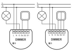
The dimmer can be used in a three-wire as well as in a two-wire system. The two wired from the mains distribution panel are connected to the inserts contacts N and L. In a three-wire system in which both contacts N and L are available in the socket, both conductors will be connected directly with this insert contacts. The contact O is the dimming output. The following circuit is realized in the three-wire system.
In a two-wire system the inserts contacts N and O are bridged and connected to the conductor coming from the fuse box. The second wire is connected to the insert contact L. It does not matter if both wires are swapped with each other. The schematics below show how to wire the actuator in a two-wire system.
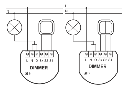
The dimmer can be operated locally using a switching paddle installed on the wall box. To connect the switching paddle with the dimmer insert it has to be connected with the insert contacts S1, S2 and Sx. Attention: There must not be mains-power connected to the insert contacts. This would immediately lead to a destruction of the dimmer..
The local operation can be realized by a single switching paddle (bistable), a double switching paddle (bistable), a single button (monostable) or a double button (monostable). The connected switch type must be selected according to the inclusion by setting the configuration parameter 14. The local switch is connected with the dimmer insert as shown in the schematics. If a bistable switch is connected it has to stay connected until the dimmer is included into the Z-Wave network.
Product Usage
The dimmer insert is able to dim different types of lights. The actuator can directly be operated by the local switching paddle. If the switch is a conventional button, every button impulse will dim the light up or down. Using a switching paddle instead of a button the operation is the same with the exception that the switching paddle has to be switched back into the OFF status afterwards manually.
The device is also able to report status changes to a controller (communication pattern 2) and to remotely operate other devices (communication pattern 5). The dimmer can be controlled by every Z-Wave device (communication pattern 1, 4 and 7). To operate other devices a second switch which does not operate the dimmer is needed.
| Reset to factory default | XXXResetDescription |
| Inclusion | Blinking red/green LED indicates that the device is in factory reset state. Once the controller is turned into inclusion mode tripple click one of the buttons on the device will include the device. A green blinking of LED will indicate successfull inclusion that will be turned off shortly afterwards. The device is excluded by tripple click to one of the buttons when the controller is in exclusion mode. |
| Exclusion | Blinking red/green LED indicates that the device is in factory reset state. Once the controller is turned into inclusion mode tripple click one of the buttons on the device will include the device. A green blinking of LED will indicate successfull inclusion that will be turned off shortly afterwards. The device is excluded by tripple click to one of the buttons when the controller is in exclusion mode. |
| NIF | XXXNIF |
| Wakeup | XXXWakeupDescription |
| Protection | XXXProtection |
| FirmwareUpdate | XXXFirmwareUpdate |
| SetAssociation | XXXSetAssociation |
Association Groups:
| Group Number | Maximum Nodes | Description |
|---|---|---|
| 3 | 1 | Report any State Change |
| 2 | 16 | external Switch No 2 |
| 1 | 16 | external Switch No 1 |
Configuration Parameters
Parameter 1: All on/off function
Enables or disabled the all on / all off function Size: 1 Byte, Default Value: ff
| Setting | Description |
|---|---|
| 00 | neither ALL ON nor ALL OFF are active |
| 01 | only ALL OFF is active |
| 02 | only ALL ON is active |
| ff | ALL ON and ALL OFF are active |
Parameter 6: Commands Sent to Association Group 1
Defines what status changes cause sending out a wireless command. Zu allow double click function parameter 14 needs to be turned to 1 Size: 1 Byte, Default Value: 00
| Setting | Description |
|---|---|
| 00 | turning on and turning off sends out a wireless command |
| 01 | Turning off sends a wireless command. All devices can be turned on using a double click, dimmers will return to their last dimming state. |
| 02 | Turning ff sends a wireless command. All devices can be turned on using a double click, dimmers will dim to 100 %. |
Parameter 7: Check status before sending a control command on external switch no 2.
When external switch no 2 is switches the status of the remote device to be switches is checked or not. Size: 1 Byte, Default Value: 01
| Setting | Description |
|---|---|
| 00 | Not checked |
| 01 | Checked |
Parameter 8: The percentage of a dimming step at automated control
The percentage drop of regulation per one dimming step with automated control Size: 1 Byte, Default Value: 01
| Setting | Description |
|---|
Parameter 9: Time between extreme values of manual dimming
The time of travel between extreme values of manual dimming level . Size: 1 Byte, Default Value: 01
| Setting | Description |
|---|
Parameter 10: Time between extreme values of automatic dimming
The time of travel between extreme values of dimming level with remote control. Size: 1 Byte, Default Value: 01
| Setting | Description |
|---|
Parameter 11: The percentage of a dimming step at manual control
The percentage drop of regulation per one dimming step with manual control Size: 1 Byte, Default Value: 01
| Setting | Description |
|---|
Parameter 12: The maximal dimming level
The maximal level of dimmeru2019s brightening Size: 1 Byte, Default Value: 63
| Setting | Description |
|---|
Parameter 13: The minimal dimming level
The minimal level of dimmeru2019s brightening Size: 1 Byte, Default Value: 02
| Setting | Description |
|---|
Parameter 14: External Switch Type
The type of switch may be chosen from mono-stable or bistable switches Size: 1 Byte, Default Value: 00
| Setting | Description |
|---|---|
| 00 | mono-stable switch |
| 01 | bistable switch |
Parameter 15: Double Click Option
Defines if the double click option is enabled. This will turn the dimmer to 100 % dimming level. Size: 1 Byte, Default Value: 01
| Setting | Description |
|---|---|
| 00 | disabled |
| 01 | enabled |
Parameter 16: Saving of the device state after power failure
Saving of the device state after the power supply black-out. The dimmer will return to the last state before the power supply black-out. Size: 1 Byte, Default Value: 01
| Setting | Description |
|---|---|
| 00 | off state |
| 01 | last dim state |
Parameter 17: Allows to double the key number 1
Stair button function allows to double the key number 1. The dimmer may operate two bistable keys or an infinite number of mono-stable keys. Size: 1 Byte, Default Value: 00
| Setting | Description |
|---|---|
| 00 | Disabled |
| 01 | Enabled |
Parameter 18: Light intensity synchronization
The function of synchronization of the light intensity for associated devices. The dimmer transmits this state to the associated device. Size: 1 Byte, Default Value: 00
| Setting | Description |
|---|---|
| 00 | Function off |
| 01 | Function on |
Parameter 19: Defines how to use bistable external switches
Bistable Switches remain in the switching state. The parameters defines how such a switch can be used for dimming. Size: 1 Byte, Default Value: 00
| Setting | Description |
|---|---|
| 00 | Every Switch on toggles the device |
| 01 | Closing external contact turns on, opening external contacts turns off |
Parameter 20: Length of the Dimmer control pulse
The function allows for lowering of the minimal dimmeru2019s level by extending of control impulse. By the means of minimal level change, the dimmer allows for the complete dimmering of LED bulbs. Not all of the LED bulbs available on the market allow dimming. Size: 1 Byte, Default Value: 6e
| Setting | Description |
|---|
Technical Data
| Dimensions | 0.0430000x0.0370000x0.0170000 mm |
| Weight | 29 gr |
| Hardware Platform | ZM3102 |
| EAN | 5902020528029 |
| IP Class | IP 20 |
| Voltage | 230V |
| Device Type | Light Dimmer Switch |
| Generic Device Class | Multilevel Switch |
| Specific Device Class | Routing Multilevel Switch |
| Firmware Version | 01.03 |
| Z-Wave Version | 03.14 |
| Certification ID | ZC08-11030010 |
| Z-Wave Product Id | 010f.0100.0103 |
| Frequency | Europe - 868,4 Mhz |
| Maximum transmission power | 5 mW |