Fibaro Group
Flood Sensor
SKU: FIB_FGFS-101
Quickstart
This is a
Inclusion, Exclusion and wakeup are confirmed by triple clicking the Z-Wave button inside the case.
Important safety information
Please read this manual carefully. Failure to follow the recommendations in this manual may be dangerous or may violate the law. The manufacturer, importer, distributor and seller shall not be liable for any loss or damage resulting from failure to comply with the instructions in this manual or any other material. Use this equipment only for its intended purpose. Follow the disposal instructions. Do not dispose of electronic equipment or batteries in a fire or near open heat sources.What is Z-Wave?
Z-Wave is the international wireless protocol for communication in the Smart Home. This device is suited for use in the region mentioned in the Quickstart section.
Z-Wave ensures a reliable communication by reconfirming every message (two-way communication) and every mains powered node can act as a repeater for other nodes (meshed network) in case the receiver is not in direct wireless range of the transmitter.
This device and every other certified Z-Wave device can be used together with any other certified Z-Wave device regardless of brand and origin as long as both are suited for the same frequency range.
If a device supports secure communication it will communicate with other devices secure as long as this device provides the same or a higher level of security. Otherwise it will automatically turn into a lower level of security to maintain backward compatibility.
For more information about Z-Wave technology, devices, white papers etc. please refer to www.z-wave.info.
Product Description
The Fibaro Flood Sensor will alert you of a threatening flood or a rapid temperature rise or drop and has a wide variety of additional functions. Thanks to its flexible gold telescopic probes the device can even work on uneven surfaces. The Flood Sensor has a built in alarm siren which will help you to react quickly in case of a flood, rapid temperature change or the attempt to tamper with it. Aside from the alarm siren, the device can alert you of a threat using colour displays from the built in RGB diode. In addition to this a tilt sensor will detect tilt and movement over 15 degrees and send out a report to the main controller. The built in temperature sensor can not only be used to serve as a fire alarm sensor, it may also be used to manage an in-floor heating system.
The Input terminal allows you to connect an external probe and install the sensor in any location. The Output terminal allows for a connection to an alarm system. The Sensor will work on 12 or 24V DC or battery.
Prepare for Installation / Reset
Please read the user manual before installing the product.
In order to include (add) a Z-Wave device to a network it must be in factory default state. Please make sure to reset the device into factory default. You can do this by performing an Exclusion operation as described below in the manual. Every Z-Wave controller is able to perform this operation however it is recommended to use the primary controller of the previous network to make sure the very device is excluded properly from this network.
Reset to factory default
This device also allows to be reset without any involvement of a Z-Wave controller. This procedure should only be used when the primary controller is inoperable.
Reset procedure deletes EPROM"s memory, including all information on the Z-Wave network and the main controller.
Fibaro Flood Sensor"s reset procedure:
1. Make sure the Sensor is powered.
2. Press and hold a TMP button for 15 - 20 seconds. LED indicator glows yellow to confirm entering 4th sub-menu.
3. Release the TMP button.
4. Click the TMP button, once.
5. The LED indicator glowing red and then turning off will confirm a successful reset. Reset completion will be confirmed by an acousic signal, same as at the power source connection.
Safety Warning for Batteries
The product contains batteries. Please remove the batteries when the device is not used. Do not mix batteries of different charging level or different brands.
Installation
There are two powering modes for the Fibaro Flood Sensor, battery or mains current. By default it"s powered by a factory included battery. In addition it can work with a constant current, after connecting a 12 / 24V DC power supply to +12 and GND terminals. Powering mode configuration is carried out automatically, while a sensor is being included into the Z-Wave network. When battery powered, a Fibaro Flood Sensor communicates with a Z-Wave network main controller periodically. Detected alarms are sent immediately, but configuration parameters and associations settings only at specified wake up intervals, or at a manual wake up (button triple click). In DC powering mode, configuration and associations parameters are sent when necessary, and in addition a sensor serves as a Z-Wave signal repeater.
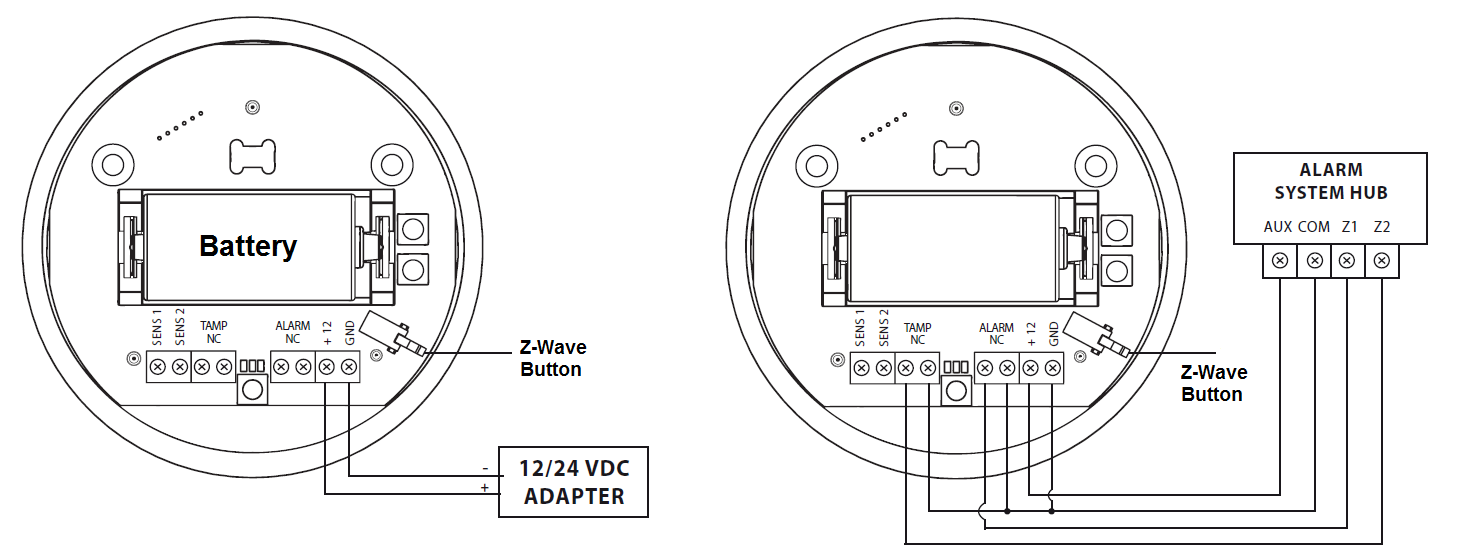
Switching to a constant current powering mode:
- Exclude a sensor from the Z-Wave network.
- Connect constant current power source (12 / 24 VDC) to +12 and GND terminals observing wiring (figure 1).
- Include the Fibaro Flood Sensor into the Z-Wave network.
In constant powering mode a sensor may operate without a battery. Installing a battery is recommended though, as it will serve as an emergency power source. When constant power fails, sensor will automatically shift to an emergency mode. All reports, including flood and temperature, will be sent immediately, but it will not be possible to modify the configuration or association settings until constant power returns. If a sensor served as a signal repeater for other Z-Wave devices, in emergency mode signal repeating function will be deactivated.
Note: Fibaro Flood Sensor will automatically exit emergency mode once 12/24 VDC at +12 and GND terminals is detected and the device wakes up after detecting an event, i.e. flood alarm, temperature report, tilt, or manual wake up using button.
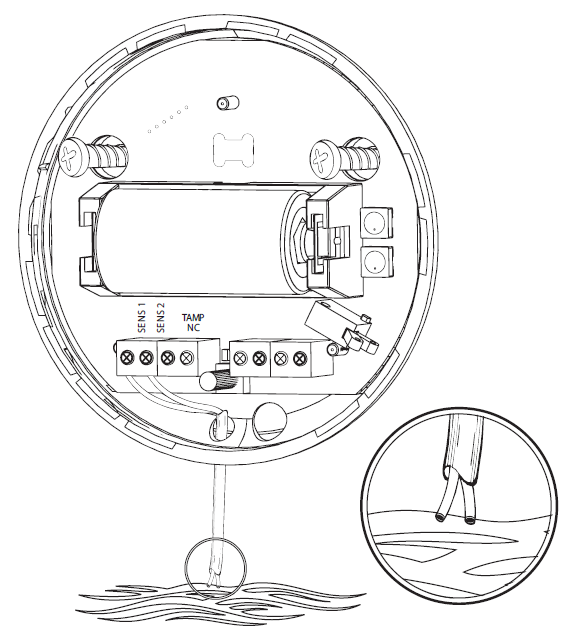
The Flood Sensor can also be used with an additional extended wire for the water sensor. Drill a hole into the casing and connect the wire as shown in figure 2.
Inclusion/Exclusion
On factory default the device does not belong to any Z-Wave network. The device needs to be added to an existing wireless network to communicate with the devices of this network. This process is called Inclusion.
Devices can also be removed from a network. This process is called Exclusion. Both processes are initiated by the primary controller of the Z-Wave network. This controller is turned into exclusion respective inclusion mode. Inclusion and Exclusion is then performed doing a special manual action right on the device.
Inclusion
Make sure that your Z-Wave Controller is in the Inclusion-/Exclusion-Mode. Tripple click the Z-Wave button inside the case to confirm the process.
Exclusion
Make sure that your Z-Wave Controller is in the Inclusion-/Exclusion-Mode. Tripple click the Z-Wave button inside the case to confirm the process.
Product Usage
Fibaro Flood Sensor has two sensors built in - flood and temperature sensors, meaning it"s a multichannel device. In the Z-Wave network"s main controller the Sensor will be shown as two devices.
Through an association Fibaro Flood Sensor may control another Z-Wave network device, e.g. a Dimmer, Relay Switch, Roller Shutter, RGBW Controller, Wall Plug, or a scene (scene only through the Home Center 2 main controller).
Fibaro Flood Sensor allows for the associations of three groups.
1-st Association Group is assigned to the device status - sending the BASIC SET (default) or ALARM control frame to the associated devices.
2-nd Association Group is assigned to a TMP button and tilt sensor - ALARM GENERIC control frame will be sent to the associated devices in case a TMP button is released or a tilt sensor triggered (depending on parameter 74 settings).
3-rd Association Group reports the device status and allows for assigning single device only (the main controller by default - the device reports its status to the main controller).
Fibaro Flood Sensor allows for controlling 5 regular and 5 multichannel devices per an association group, out of which 1 field is reserved for the Z-Wave network main controller.
Z-Wave Range Test
Fibaro Flood Sensor has a built in Z-Wave network range test for the main controller. Follow the instruction to test the main controller"s range:
- Press and hold a TMP button for 10 - 15 seconds, until a LED indicator colour changes to violet.
- Release the TMP button.
- Click the TMP button again.
- LED indicator will signal the Z-Wave network range (see description below).
- To exit the Range Tester click the TMP button.
Z-Wave Range Tester signaling modes:
LED Indicator pulsing green - Fibaro Flood Sensor attempts to directly communicate with the main controller. If the direct communication attempt fails, the sensor will try routed communication, through other devices, which will be signaled with LED Indicator blinking yellow.
LED Indicator glowing green - Fibaro Flood Sensor directly communicating with the main controller.
LED Indicator pulsing yellow - Fibaro Flood Sensor tries to establish routed connection with the main controller, through intermediary devices.
LED Indicator glowing yellow - Fibaro Flood Sensor communicates with the main controller through other, intermediary devices. After two seconds the Sensor will retry to directly connect to the main controller, which will be signaled with the Indicator pulsing green.
LED Indicator pulsing violet - Fibaro Flood Sensor communicates at the range limit. If connection proves successful it will be confirmed with a yellow glow. It"s not recommended to use the sensor at the range limit.
LED Indicator glowing red - Fibaro Flood Sensor unable to connect to the main controller directly or through another Z-Wave network nodes.
Node Information Frame
The Node Information Frame (NIF) is the business card of a Z-Wave device. It contains information about the device type and the technical capabilities. The inclusion and exclusion of the device is confirmed by sending out a Node Information Frame. Beside this it may be needed for certain network operations to send out a Node Information Frame. To issue a NIF execute the following action:
Tripple click on the Z-Wave button inside the case or a detection by one of the sensors will send a Node Information Frame.
Communication to a Sleeping device (Wakeup)
This device is battery operated and turned into deep sleep state most of the time to save battery life time. Communication with the device is limited. In order to communicate with the device, a static controller C is needed in the network. This controller will maintain a mailbox for the battery operated devices and store commands that can not be received during deep sleep state. Without such a controller, communication may become impossible and/or the battery life time is significantly decreased.
This device will wakeup regularly and announce the wakeup state by sending out a so called Wakeup Notification. The controller can then empty the mailbox. Therefore, the device needs to be configured with the desired wakeup interval and the node ID of the controller. If the device was included by a static controller this controller will usually perform all necessary configurations. The wakeup interval is a tradeoff between maximal battery life time and the desired responses of the device. To wakeup the device please perform the following action:
Tripple click on the Z-Wave button inside the case will wake up the device.
Quick trouble shooting
Here are a few hints for network installation if things dont work as expected.
- Make sure a device is in factory reset state before including. In doubt exclude before include.
- If inclusion still fails, check if both devices use the same frequency.
- Remove all dead devices from associations. Otherwise you will see severe delays.
- Never use sleeping battery devices without a central controller.
- Dont poll FLIRS devices.
- Make sure to have enough mains powered device to benefit from the meshing
Association - one device controls an other device
Z-Wave devices control other Z-Wave devices. The relationship between one device controlling another device is called association. In order to control a different device, the controlling device needs to maintain a list of devices that will receive controlling commands. These lists are called association groups and they are always related to certain events (e.g. button pressed, sensor triggers, ...). In case the event happens all devices stored in the respective association group will receive the same wireless command wireless command, typically a 'Basic Set' Command.
Association Groups:
| Group Number | Maximum Nodes | Description |
|---|---|---|
| 1 | 5 | Flood Alarm with BASIC SET |
| 2 | 5 | Tilt Sensor alarm and TMP button events |
| 3 | 1 | reports device status |
Configuration Parameters
Z-Wave products are supposed to work out of the box after inclusion, however certain configuration can adapt the function better to user needs or unlock further enhanced features.
IMPORTANT: Controllers may only allow configuring signed values. In order to set values in the range 128 ... 255 the value sent in the application shall be the desired value minus 256. For example: To set a parameter to 200 it may be needed to set a value of 200 minus 256 = minus 56. In case of a two byte value the same logic applies: Values greater than 32768 may needed to be given as negative values too.
Parameter 1: Alarm cancellation delay
Delays flood alarm cancelation for the device after flooding has ceased Size: 2 Byte, Default Value: 0000
| Setting | Description |
|---|
Parameter 2: Acoustic and visual signals On / Off in case of flooding
parameter allows for LED indicator and acoustic alarm deactivation in case of flooding detection Size: 1 Byte, Default Value: 03
| Setting | Description |
|---|---|
| 00 | acoustic and visual alarms inactive |
| 01 | acoustic alarm inactive, visual alarm active |
| 02 | acoustic alarm active, visual alarm inactive |
| 03 | acoustic and visual alarms active |
Parameter 5: Type of alarm frame sent to 1-st association group (FLOOD)
parameter determines a type of command frame sent by the Sensor in case flooding has been detected or cancelled Size: 1 Byte, Default Value: 81
| Setting | Description |
|---|---|
| 00 | ALARM WATER command frame |
| 81 | BASIC SET command frame |
Parameter 7: Forced dimming level sent to 1-st association group devices
Forced dimming level / roller blind opening level, when sending turn on / open Size: 1 Byte, Default Value: 63
| Setting | Description |
|---|
Parameter 9: Alarm cancelling or turning a device off (Basic) command frame deactivation
Allows for deactivating device turn off and alarm cancellation functions for the devices assigned to 1-st association group Size: 1 Byte, Default Value: 00
| Setting | Description |
|---|---|
| 00 | Alarm (flooding) cancellation inactive |
| 01 | Alarm (flooding) cancellation active |
Parameter 10: Temperature measurement interval
Time interval, in seconds, between consecutive temperature measurements Size: 2 Byte, Default Value: 012c
| Setting | Description |
|---|
Parameter 12: Temperature measurement hysteresis
Determines a minimum temperature change value (insensitivity level), resulting in a temperature report being sent Size: 2 Byte, Default Value: 0032
| Setting | Description |
|---|
Parameter 13: Alarm BROADCAST
Value other than 0 means alarms are sent in BROADCAST mode (with a priority over other communicates), to all devices within the Sensoru2019s range Size: 1 Byte, Default Value: 00
| Setting | Description |
|---|---|
| 00 | broadcasts inactive |
| 01 | flood (1-st Association Group) broadcast active; tamper (2-nd Association Group) broadcast inactive |
| 02 | flood broadcast inactive; tamper broadcast active |
| 03 | flood broadcast active; tamper broadcast active |
Parameter 50: Low temperature alarm threshold
parameter stores a temperature value, below which LED indicator blinks with a definable colour Size: 2 Byte, Default Value: 05dc
| Setting | Description |
|---|
Parameter 51: High temperature alarm threshold
parameter stores a temperature value, above which LED indicator blinks with a definable colour Size: 2 Byte, Default Value: 0dac
| Setting | Description |
|---|
Parameter 61: Low temperature alarm indicator LED colour
Parameter stores RGB colour value Size: 4 Byte, Default Value: 000000ff
| Setting | Description |
|---|
Parameter 62: High temperature alarm indicator LED colour
Parameter stores RGB colour value Size: 4 Byte, Default Value: 00ff0000
| Setting | Description |
|---|
Parameter 63: Managing a LED indicator under standard operation
Parameter determines LED indicatoru2019s operation. Set to 0 turns the indicator off, saving a battery life Size: 1 Byte, Default Value: 02
| Setting | Description |
|---|---|
| 00 | LED indicator doesnu2019t indicate the temperature |
| 01 | LED indicator indicates the temperature (blink) every Temperature Measurement Interval (Parameter 10, constant current and battery) or Wake Up Interval (battery mode) |
| 02 | LED indicator indicates the temperature continuously, only in constant power mode |
Parameter 73: Temperature measurement compensation
Parameter stores a temperature value to be added to or deducted from the current temperature measured to compensate temperature deflection Size: 2 Byte, Default Value: 0000
| Setting | Description |
|---|
Parameter 74: Alarm frame sent to 2-nd Association Group activation
parameter to device wich sensors send Alarm to 2. association group Size: 1 Byte, Default Value: 02
| Setting | Description |
|---|---|
| 00 | tamper alarms inactive |
| 01 | button tamper alarm active |
| 02 | movement tamper alarm active |
| 03 | button and movement tampers alarm active |
Parameter 75: Visual and audible alarms duration
parameter determines a time period after which visual and audible alarm will become u201cquietu201d Size: 2 Byte, Default Value: 0000
| Setting | Description |
|---|
Parameter 76: Alarm frame / Basic Set frame retransmission time when retaining flood alarm
Parameter determines a time period after which an alarm frame will be retransmitted Size: 2 Byte, Default Value: 0000
| Setting | Description |
|---|
Parameter 77: Flood sensor functionality turned off
Allows for turning off the internal flood sensor. Tamper and built in temperature sensor will remain active. Size: 1 Byte, Default Value: 00
| Setting | Description |
|---|---|
| 00 | Default flood sensor operation (flood detection, reactions) |
| 01 | Built in flood sensor TURNED OFF (doesnu2019t change its state in the main controller, doesnu2019t send Alarms and Basic Set frames with flood state changes. Always visible in the main controller as turned off) |
Technical Data
| Dimensions | 0.0650000x0.0650000x0.0280000 mm |
| Weight | 41 gr |
| EAN | 5902020528142 |
| Battery Type | 1 * CR123 |
| Firmware Version | 17.17 |
| Z-Wave Version | 03.34 |
| Certification ID | ZC08-14040015 |
| Z-Wave Product Id | 010f.0b00.1001 |
| Frequency | Europe - 868,4 Mhz |
| Maximum transmission power | 5 mW |
Supported Command Classes
- Multi Channel
- Basic
- Wake Up
- Association
- Version
- Sensor Binary
- Battery
- Multi Channel Association
- Configuration
- Manufacturer Specific
- Firmware Update Md
- Sensor Alarm
Explanation of Z-Wave specific terms
- Controller — is a Z-Wave device with capabilities to manage the network. Controllers are typically Gateways,Remote Controls or battery operated wall controllers.
- Slave — is a Z-Wave device without capabilities to manage the network. Slaves can be sensors, actuators and even remote controls.
- Primary Controller — is the central organizer of the network. It must be a controller. There can be only one primary controller in a Z-Wave network.
- Inclusion — is the process of adding new Z-Wave devices into a network.
- Exclusion — is the process of removing Z-Wave devices from the network.
- Association — is a control relationship between a controlling device and a controlled device.
- Wakeup Notification — is a special wireless message issued by a Z-Wave device to announces that is able to communicate.
- Node Information Frame — is a special wireless message issued by a Z-Wave device to announce its capabilities and functions.