Fibaro Group
Door/ Window Sensor with Temperature Sensor Option
SKU: FIB_FGK-101

Quickstart
This is a
For Inclusion and Exclusion, sending out a NIF or wakeup the device push down the tamper switch (push the device on a table) if the device is not yet mounted. Then hit the little button (B) inside of the enclosure one time.
Important safety information
Please read this manual carefully. Failure to follow the recommendations in this manual may be dangerous or may violate the law. The manufacturer, importer, distributor and seller shall not be liable for any loss or damage resulting from failure to comply with the instructions in this manual or any other material. Use this equipment only for its intended purpose. Follow the disposal instructions. Do not dispose of electronic equipment or batteries in a fire or near open heat sources.Product Description
The Fibaro Door / Window Sensor is a battery powered, Z-Wave compatible reed sensor. It combines the functionality of 3 devices (reed, binary and temperature sensor) in one easy to use product. The sensor can be used for monitoring whether a door, window, window blind or a garage gate is open or closed. In addition, you can integrate any binary output sensor with the Z-Wave network using this sensor, e.g. motion sensors, flood sensors, alarm system sensors, etc.
The product consists of two elements. One of the parts is mounted on the moving part of the window or of the door. The other part is placed on the frame. The device needs to be included into a Z-Wave network by a remote control or any other Z-Wave controller. If an action is detected, the sensor sends a signal to the Z-Wave network main controller.
Installation
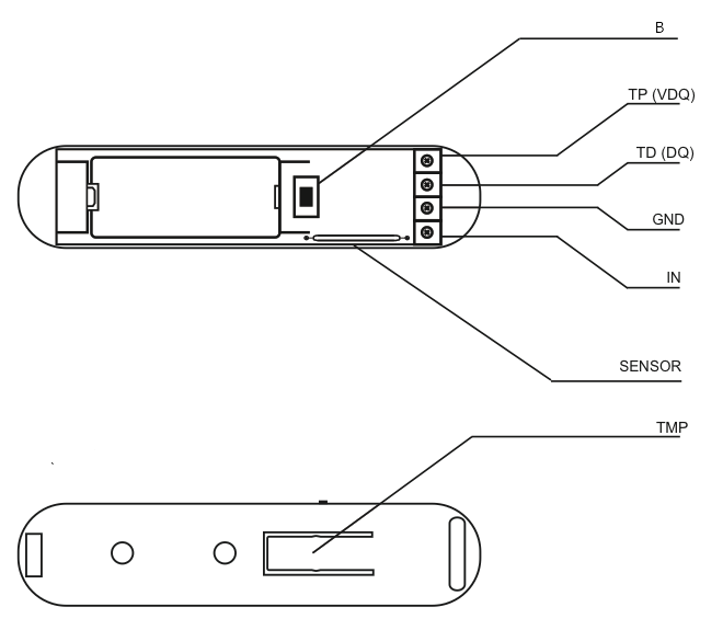
The sensor consists of two parts: The sensor main device plus a little magent that is triggering the sensor when closed to the main device. One part of the sensor is mounted on the fixed part of the door or window while the other part is mounted on the moving part in a way, that both devices are adjacent to each other with no more than 5 mm distance between them. The main device can be mounted with double sided tape however for security applications it is strongly recommended to use screws. The holes to screw the device are placed behind the battery. Hence the battery need to be removed for this procedure. The image shows the two buttons "TMP" and "B", the reed sensor and the contact terminal for external switches and sensors.
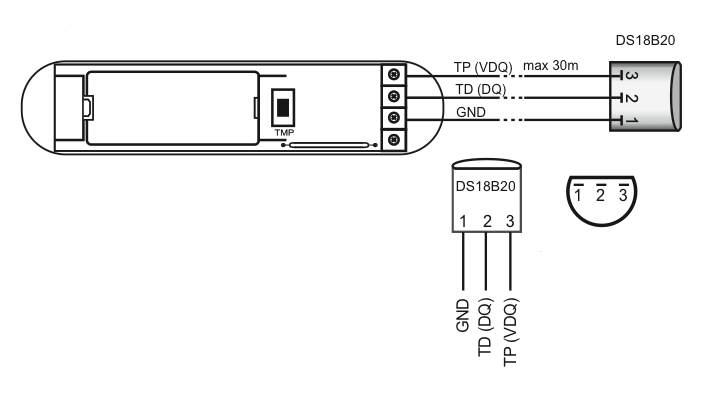
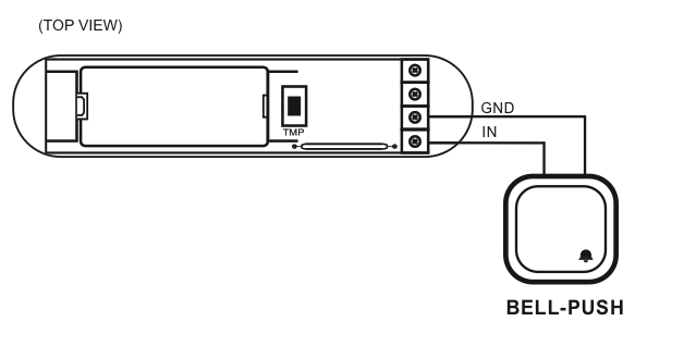
The external temperature sensor DS18B20 is connected to the device as shown in this picture. In case the sensor shall only act as temperature sensor it can be placed everywhere and there is no need to place the magnet nearby. Beside to act as temperature sensor the device can also work as simple digial sensor transmitting the status of an externally connected on/off switch. The subsequent image shows how to connect such an external switch to the pins "IN" and "GND".
Product Usage
The sensor reports status changes and - if a external temperature sensor is attached - the temperature using wireless Z-Wave commands. There is no further local interaction needed or possible.
| Reset to factory default | XXXResetDescription |
| Inclusion | For Inclusion and Exclusion push down the tamper switch (push the device on a table) if the device is not yet mounted. Then hit the little button (B) inside of the enclosure one time. |
| Exclusion | For Inclusion and Exclusion push down the tamper switch (push the device on a table) if the device is not yet mounted. Then hit the little button (B) inside of the enclosure one time. |
| NIF | For sending out a node information frame push down the tamper switch (push the device on a table) if the device is not yet mounted.Then hit the little button (B) inside of the enclosure one time. |
| Wakeup | To wake up the device push down the tamper switch (push the device on a table) if the device is not yet mounted. Then hit the little button (B) inside of the enclosure one time. |
| Protection | XXXProtection |
| FirmwareUpdate | XXXFirmwareUpdate |
| SetAssociation | XXXSetAssociation |
Association Groups:
| Group Number | Maximum Nodes | Description |
|---|---|---|
| 1 | 5 | Group I is assigned to input IN1 (and the magnetic sensor). Sending BASIC SET or ALARM command frames. |
| 2 | 5 | Group II is assigned to TMP button. Once the button is released, ALARM GENERIC frame is sent to associated devices. |
| 3 | 1 | Group III reports on the condition of the device, only one device may be assigned to the group (main controller, by default). |
Configuration Parameters
Parameter 1: Input IN alarm cancellation delay
Additional delay after an alarm from input IN has ceased. The parameter allows user to specify additional time, after which the input IN alarm is cancelled once its violation has ceased. Size: 2 Byte, Default Value: 0000
| Setting | Description |
|---|
Parameter 2: Status change signalled by LED
Size: 1 Byte, Default Value: 00
| Setting | Description |
|---|---|
| 00 | LED turned Off |
| 01 | LED turned On |
Parameter 3: Type of IN input
Size: 1 Byte, Default Value: 00
| Setting | Description |
|---|---|
| 00 | Normal Close |
| 01 | Normal Open |
| 02 | Mono Stable |
| 03 | bistable |
Parameter 5: Type of control frame transmitted for association group 1, activated via IN input
The parameter allows you to specify the type of an alarm frame or to force control frames transmission (BASIC_SET) Size: 1 Byte, Default Value: ff
| Setting | Description |
|---|---|
| 00 | ALARM GENERIC frame |
| 01 | ALARM SMOKE frame |
| 02 | ALARM CO frame |
| 03 | ALARM CO2 frame |
| 04 | ALARM HEAT frame |
| 05 | ALARM WATER frame |
| ff | Control frame BASIC_SET |
Parameter 7: Value of the parameter specifying the forced level of dimming/opening roller blinds when u201cswitch onu201d/u201dopenu201d commands are sent to devices from association group no.1
In case of alarm frames an alarm priority is specified. Value of 255 makes it possible to activate a device. In case of the Dimmer module it means activating the device and setting it to the previously stored condition, e.g. when Dimmer is set to 30%, deactivated and then reactivated using 255 commend, it will be automatically set to the previous condition i.e. 30%. Size: 1 Byte, Default Value: ff
| Setting | Description |
|---|---|
| 01 - 63 | Dimming level |
| ff | Turn On |
Parameter 9: Deactivating transmission of the alarm cancelling frame or the control frame deactivating the device (Basic)
It allows for disabling the function of deactivating the device and cancelling alarms for devices associated with IN input. Size: 1 Byte, Default Value: 00
| Setting | Description |
|---|---|
| 00 | for association group no. 1 information is sent |
| 01 | for association group no. 1 information is not sent |
Parameter 12: Sensitivity to temperature changes
The maximum acceptable difference between the last reported temperature and the current temperature read from the sensor. If the temperatures differ by the set value or more, a report with the current temperature value is sent to the device assigned to association group no. 3. To set an appropriate parameter value use the following formula: x = delta T x 16 - for Celsius; x = delta T x 80 / 9 - for Fahrenheit; x = parameter value; delta T - maximum acceptable temperature gradient in Celsius or Fahrenheit. If the value is set to 0: - if the wake-up interval is set to 255 seconds, temperature report will be sent according to the interval; - if the wake-up interval is set to over 255, temperature report will be sent each ca. 4 minutes. Available parameter settings: 0 - 255 [0oC to 16oC] [32oF - 60,8oF] Size: 1 Byte, Default Value: 08
| Setting | Description |
|---|
Parameter 13: Sending an alarm or control frame (for IN input, depending on parameter no.5 value), and TMP button alarm frame
The frame is sent in u201cbroadcastu201d mode, i.e. to all devices within range - information sent in this mode is not repeated by the mesh network. Size: 1 Byte, Default Value: 00
| Setting | Description |
|---|---|
| 00 | IN and TMP Broadcast mode inactive |
| 01 | IN broadcast mode active, TMP broadcast mode inactive |
| 02 | IN broadcast mode inactive, TMP broadcast mode active |
| 03 | IN and TMP broadcast mode active |
Parameter 14: Scene activation functionality
IN input: Switch from u201coffu201d to u201conu201d ID10; Switch from u201conu201d to u201coffu201d ID11; Remaining IDs are recognized correctly if the value of parameter no.3 was set to 2 Holding down ID12; Releasing ID13; Double click ID14; Triple click ID 15; Scene activation functionality may shorten the battery life, even by 25%. Size: 1 Byte, Default Value: 00
| Setting | Description |
|---|---|
| 00 | functionality deactivated |
| 01 | functionality activated |
Technical Data
| Dimensions | 0.0180000x0.0750000x0.0190000 mm |
| Weight | 10 gr |
| Hardware Platform | ZM3102 |
| EAN | 5902020528111 |
| Battery Type | 1 * CR2 |
| Device Type | Routing Binary Sensor |
| Generic Device Class | Binary Sensor |
| Specific Device Class | Routing Binary Sensor |
| Firmware Version | 02.01 |
| Z-Wave Version | 03.2a |
| Certification ID | ZC08-14060004 |
| Z-Wave Product Id | 010f.0700.1000 |
| Frequency | Europe - 868,4 Mhz |
| Maximum transmission power | 5 mW |