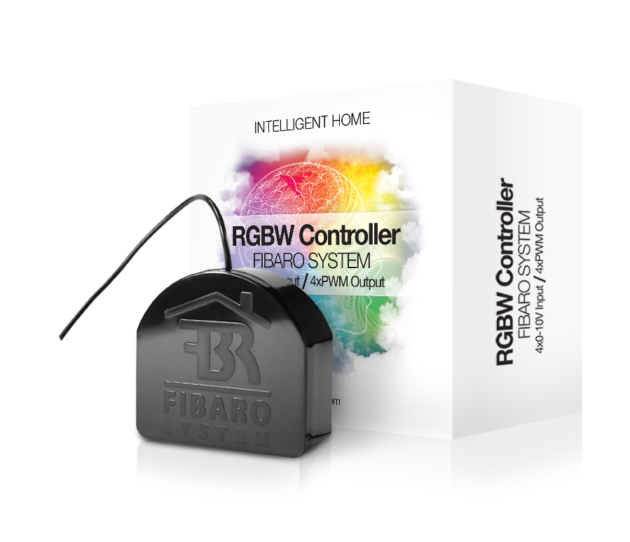
Fibaro Group
RGB Module
SKU: FIB_FGRGB-101
Quickstart
This is a
Triple click the B-button or any switch connected to I1-I4 inputs confirms Inclusion or Exclusion. The device turns into autoinclusion mode when powered up the first time.
Important safety information
Please read this manual carefully. Failure to follow the recommendations in this manual may be dangerous or may violate the law. The manufacturer, importer, distributor and seller shall not be liable for any loss or damage resulting from failure to comply with the instructions in this manual or any other material. Use this equipment only for its intended purpose. Follow the disposal instructions. Do not dispose of electronic equipment or batteries in a fire or near open heat sources.Product Description
The Fibar RGBW Module allows controlling 4-color LED strips via Z-Wave wirelessly and locally utilizing a traditional wall switch. Beside the traditional RGB channels it also supports an additional white light channel, which allows adding pastel to the colour scheme. The device is placed in a wall box right behind the normal switch. The switch is not longer directly connected to the load but acts as an input device for the Fibar insert that is controlling the load. The solution works with all switch designs or potentiometers with or without neutral position as long as there is enough space in the wall box behind the switch. The device is just 15 mm height. The available space depends on the size of the traditional switch, the dimensions of the wall box and the amount of additional cabling placed in this box. The device must be powered by a 12 V external power supply.
Installation
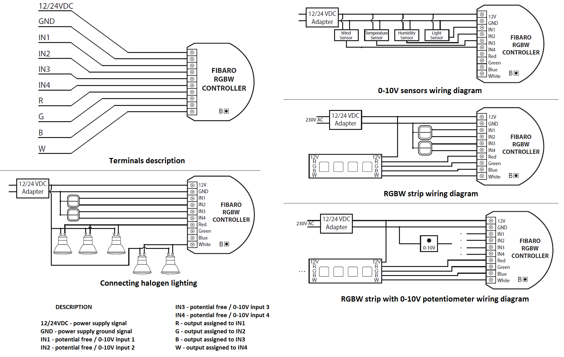
- Before installation ensure the voltage supply is disconnected.
- Connect Fibaro RGBW Controller according to wiring diagram. First, connect outputs (R,G,B,W) RGB/RGBW/LED diodes or Halogen lights, or inputs (I1-I4). Second, connect voltage supply.
- The device must be powered by a dedicated stabilized power adapter (12V / 24V DC).
- Turn the voltage on.
- Include the module into the Z-Wave network.
Note:
- Fibaro RGBW Controller is dedicated to operate in low voltage circuits of 12VDC or 24VDC. Connecting higher voltage load may result in Fibaro RGBW Controller damage.
- Fibaro RGBW Controller must be powered by the same voltage as the connected light source. I.e. if controlling 12V LED strip, the module must be connected to 12V power supply. Similarly, if controlling 24V RGBW strip, Fibaro RGBW Controller must be powered by 24V voltage supply.
- Fibaro RGBW Controller has 0-10V input. There is no 0-10V output. Output is controlled by PWM at 244Hz.
- Sensors using 0-10V interface use wire connection to inputs I1 - I4. Maximum length of 0-10V connection line is 10 m. Observe sensor"s manufacturer recommendations towards 0-10V line diameter.
- In case of connecting long RGBW/RGB/LED strips voltage drops may occur, resulting in lower light brightness further from R/G/B/W outputs. To eliminate this effect it"s recommended to connect few shorter strips in serial connection instead of one long strip connected parallel. Maximum recommended wire length, used to connect R/G/B/W outputs with a RGBW/RGB/LED strip is 10 m. Observe connected loads manufacturer recommendations towards connection wire diameter.
Product Usage
The device may be controller by momentary or toggle switches. Fibaro RGBW Controller may serve as 0-10V input module and operate with any 0-10V sensor, e.g. temperature sensors, wind speed/direction sensors, air quality sensors, light sensors, etc.
Fibaro RGBW Controller offers fully configurable operating modes, user defined in parameter 14. Operating mode is set during first configuration in Home Center 2 interface. Other main controllers require dedicated setting of parameter 14.
Fibaro RGBW Controller"s operating modes:
RGB/RGBW MODE - controlling RGBW/RGB/LED strips or Halogen lights based on signals from switches connected to I1-I4 inputs. User may precisely set illumination colour.
Fibaro RGBW Controller has 4 controllable inputs I1-I4, configured by default to work with push buttons. Each input controls designated channel, i.e.:
- I1 controls R channel
- I2 controls G channel
- I3 controls B channel
- I4 controls W channel
Controlling I1-I4 inputs is achieved by connecting ground wire (GND) to specified channel (see scheme). Further, parameter"s 14 settings allow for following type of manual control:
- NORMAL mode - controlling output assigned to given input terminal. In this setting outputs will be controlled independently from one another, e.g. allowing for free adjusting each colours saturation. Double click will set a given channel"s saturation to 100%. This operating mode works with momentary and toggle switches.
- BRIGHTNESS mode - all outputs are controlled together, i.e. one switch controls brightness of all channels at the same time. This operating mode works with momentary and toggle switches.
- RAINBOW mode - 3. mode - all outputs are controlled together giving a transition of full colours spectrum. RAINBOW mode works with momentary switches only.
IN/OUT MODE - all inputs and outputs may be freely configured by the user. All inputs I1 - I4 and outputs R, G, B, W may be independently configured by the user. Depending on configuration the device will be presented in Home Center 2 interface as sensors or dimmers. User defines sensor type and its operating range. If a given channel operates in OUT mode, user may control e.g. LED or Halogen lamp brightness.
Fibaro RGBW Controller has 4 controllable, analog inputs I1 - I4, allowing for 0-10V analog signal interpretation. This functionality may be used in operation with analog sensors and potentiometers. What"s more, in IN/OUT mode all inputs and outputs may be configured independently, e.g. I1 may be configured as 0-10V sensor input and I2-I4 may control LED strip or Halogen lamps.
Another option is to configure I1 as 0-10V input and connect 0-10V potentiometer to it, and connecting Halogen lamps to R output. At the same time, other inputs may work with 0-10V sensors.
Current load and energy consumption:
Fibaro RGBW Controller allows for the current load and power consumption monitoring. Data is sent to the main controller.
Electric power - power consumed by an electric device in an instant, in Watts (W).
Electric energy - energy consumed by a device through a time period. Most commonly measured in kilowatt-hours (kWh). One kilowatt-hour is equal to one kilowatt of power consumed over a period of one hour, 1kWh = 1000 Wh.
| Reset to factory default | Reset procedure clears the Fibaro RGBW Controller"s memory, including Z-Wave network controller information, energy consumption data and 5 user-defined programs. Resetting Fibaro RGBW Controller:
|
| Inclusion | For inclusion/exclusion of the device triple click the B-button or any switch connected to I1-I4 inputs. Further you can use the auto-inclusion mode by setting the Home Center controller into the inclusion mode and then connect voltage supply to auto-include Fibaro RGBW Controller. |
| Exclusion | For inclusion/exclusion of the device triple click the B-button or any switch connected to I1-I4 inputs. Further you can use the auto-inclusion mode by setting the Home Center controller into the inclusion mode and then connect voltage supply to auto-include Fibaro RGBW Controller. |
| NIF | XXXNIF |
| Wakeup | XXXWakeupDescription |
| Protection | XXXProtection |
| FirmwareUpdate | XXXFirmwareUpdate |
| SetAssociation | For association bring your controller in the association mode and triple click the B-button or any switch connected to I1-I4 inputs. |
Association Groups:
| Group Number | Maximum Nodes | Description |
|---|---|---|
| 1 | 5 | assigned to IN1 input - sends control frame to associated devices each time the device state changes (ON/OFF) |
| 2 | 5 | assigned to IN2 input - sends control frame to associated devices each time the device state changes (ON/OFF) |
| 3 | 5 | assigned to IN3 input - sends control frame to associated devices each time the device state changes (ON/OFF) |
| 4 | 5 | assigned to IN4 input - sends control frame to associated devices each time the device state changes (ON/OFF) |
| 5 | 1 | reports device status. Only one device may be assigned to this group, main controller by default |
Configuration Parameters
Parameter 1: ALL ON / ALL OFF function activation
Activation/deactivation of ALL ON/ALL OFF functions Size: 1 Byte, Default Value: 255
| Setting | Description |
|---|---|
| 0 | ALL ON inactive ALL OFF inactive |
| 1 | ALL ON inactive ALL OFF active |
| 2 | ALL ON active ALL OFF inactive |
| 255 | ALL ON active ALL OFF active |
Parameter 6: Associations command class choice
Size: 1 Byte, Default Value: 0
| Setting | Description |
|---|---|
| 0 | Normal (Dimmer) - BASIC_SET/SWITCH_MULTILEVEL_START/STOP |
| 1 | Normal (RGBW) - COLOR_CONTROL_SET/START/STOP_STATE_CHANGE |
| 2 | Normal (RGBW) - COLOR_CONTROL_SET |
| 3 | Brightness - BASIC_SET/SWITCH_MULTILEVEL_START/STOP |
| 4 | Rainbow (RGBW) - COLOR_CONTROL_SET |
Parameter 8: Outputs state change mode
MODE1, Example: change saturation level from 0% to 99%, Size: 1 Byte, Default Value: 0
| Setting | Description |
|---|---|
| 0 | MODE1 (related parameters: 9-step value, 10-time between steps) |
| 1 | MODE2 (related parameters: 11-time to change value, relevant for RGB/RGBW) |
Parameter 9: Step value (relevant for MODE1)
Size: 1 Byte, Default Value: 1
| Setting | Description |
|---|
Parameter 10: Time between steps (relevant for MODE1)
Size: 2 Byte, Default Value: 10
| Setting | Description |
|---|---|
| 1 - 60000 | 1- 60000 ms |
Parameter 11: Time for changing from start to end value
Size: 1 Byte, Default Value: 67
| Setting | Description |
|---|---|
| 0 | immediate change |
| 01 - 63 | 20-126 [ms] value*20ms |
| 65 - 127 | 1-63 [s] (value-64)*1s |
| 129 - 191 | 10-630 [s] (value-128)*10s |
| 193 - 255 | 1-63 [min] (value-192)*1min |
Parameter 12: Maximum lighting level
Maximum brightening level cannot be lower than Minimum dimmming level. Size: 1 Byte, Default Value: 255
| Setting | Description |
|---|
Parameter 13: Minimum lighting level
Minimum dimmming level cannot be higher than Maximum brightening level. Size: 1 Byte, Default Value: 2
| Setting | Description |
|---|
Parameter 14: Inputs/Outputs configuration
Parameter is relevant for main controllers other than Home Center only. Each 4bit refers to given IN/OUT (channel) settings. Size: 2 Byte, Default Value: 4369
| Setting | Description |
|---|
Parameter 16: Restore switch state after power cycle
Defines if the switch should restore switch state to the last state prior to device power off (power cycle). Size: 1 Byte, Default Value: 1
| Setting | Description |
|---|---|
| 0 | the device does not save the state before a power failure and turns off the load |
| 1 | the device restores its state before power failure |
Parameter 30: Alarm of any type
General alarm, flood alarm, smoke alarm CO, CO2, temperature alarm Size: 1 Byte, Default Value: 0
| Setting | Description |
|---|---|
| 0 | INACTIVE - the device doesnt respond to alarm frames |
| 1 | ALARM ON - the device turns on once alarm is detected (all channels set to 99%) |
| 2 | ALARM OFF - the device turns off once alarm is detected (all channels set to 0%) |
| 3 | ALARM PROGRAM - alarm sequence turns on (program selected in parameter 38) |
Parameter 38: Alarm sequence program
Size: 1 Byte, Default Value: 10
| Setting | Description |
|---|---|
| 1 - 10 | specifies alarm program number |
Parameter 39: Active PROGRAM alarm time
Size: 2 Byte, Default Value: 600
| Setting | Description |
|---|---|
| 1 - 65534 | in seconds |
Parameter 42: Command class reporting Outputs status change
Size: 1 Byte, Default Value: 0
| Setting | Description |
|---|---|
| 0 | Reporting as a result of inputs and controllers actions (SWITCH MULTILEVEL) |
| 1 | Reporting as a result of inputs actions (SWITCH MULTILEVEL) |
| 2 | Reporting as a result of inputs actions (COLOR CONTROL) |
Parameter 43: Reporting 0-10v analog inputs change threshold
Parameter defines a value by which input voltage must change in order to be reported to the main controller. New value is calculated based on last reported value. Size: 1 Byte, Default Value: 5
| Setting | Description |
|---|---|
| 1 - 100 | 1-100 (0.1 -100V) |
Parameter 44: Power load reporting frequency
Time between reports. The report will be sent if last reported value differs from the current value, else reports will also be sent in case of polling. Size: 2 Byte, Default Value: 30
| Setting | Description |
|---|---|
| 0 | Reports are not sent. Reports will only be sent in case of polling or at turning OFF the device. |
| 1 - 65534 | sec |
Parameter 45: Reporting changes in energy consumed by controlled devices.
New reported energy value is calculated based on last reported value. Size: 1 Byte, Default Value: 10
| Setting | Description |
|---|---|
| 0 | changes in consumed energy will not be reported. Reports will be sent only in case of polling. |
| 1 - 254 | 0.01kWh |
Parameter 71: Response to BRIGHTNESS set to 0%
Size: 1 Byte, Default Value: 1
| Setting | Description |
|---|---|
| 0 | illumination colour set to white (all channels controlled together) |
| 1 | last set colour is memorized |
Parameter 72: Starting predefined program when device set to work in RGB/RGBW mode
Parameter is relevant for main controllers other than Home Center only. Size: 1 Byte, Default Value: 01
| Setting | Description |
|---|---|
| 1 - 10 | animation programm number |
Parameter 73: Triple click action
Size: 1 Byte, Default Value: 0
| Setting | Description |
|---|---|
| 0 | NODE INFO control frame is sent |
| 1 | starting favourite program |
Technical Data
| Dimensions | 0.0380000x0.0420000x0.0180000 mm |
| Weight | 30 gr |
| EAN | 5902020528159 |
| Device Type | Light Dimmer Switch |
| Generic Device Class | Multilevel Switch |
| Specific Device Class | Routing Multilevel Switch |
| Firmware Version | 16.16 |
| Z-Wave Version | 03.34 |
| Certification ID | ZC08-14060006 |
| Z-Wave Product Id | 010f.0900.4000 |
| Frequency | Europe - 868,4 Mhz |
| Maximum transmission power | 5 mW |