Fibaro Group
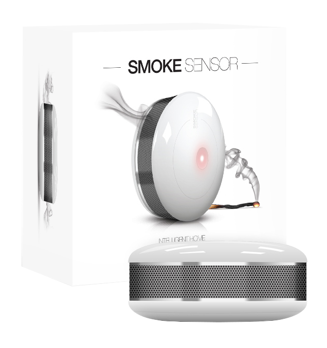
Smoke Sensor
SKU: FIB_FGSS-101
Quickstart
This is a
To include the device into the network, turn the controller into the inclusion mode and then triple click the B-button on the casing. Further you can use the auto-inclusion mode by setting the controller into the inclusion mode and then connect the constant current voltage supply. Auto-inclusion only works in constant current mode.
Important safety information
Please read this manual carefully. Failure to follow the recommendations in this manual may be dangerous or may violate the law. The manufacturer, importer, distributor and seller shall not be liable for any loss or damage resulting from failure to comply with the instructions in this manual or any other material. Use this equipment only for its intended purpose. Follow the disposal instructions. Do not dispose of electronic equipment or batteries in a fire or near open heat sources.Product Description
The new Z-Wave based Smoke Sensor is an ultra light device, that is battery and 12/24 V DC powered for maximum protection from flaming and smoldering fires. It has two alarm indicators: built-in siren and RGB visual indicator. The 65 (diameter) x 28 (height) mm Smoke Sensor features a built-in electronic recording device, facilitating an investigation of fire accidents. Attention: This is no Smoke detector according to DIN EN 14604. The device may not comply with local regulations for fire prevention.
Installation
POWERING MODES
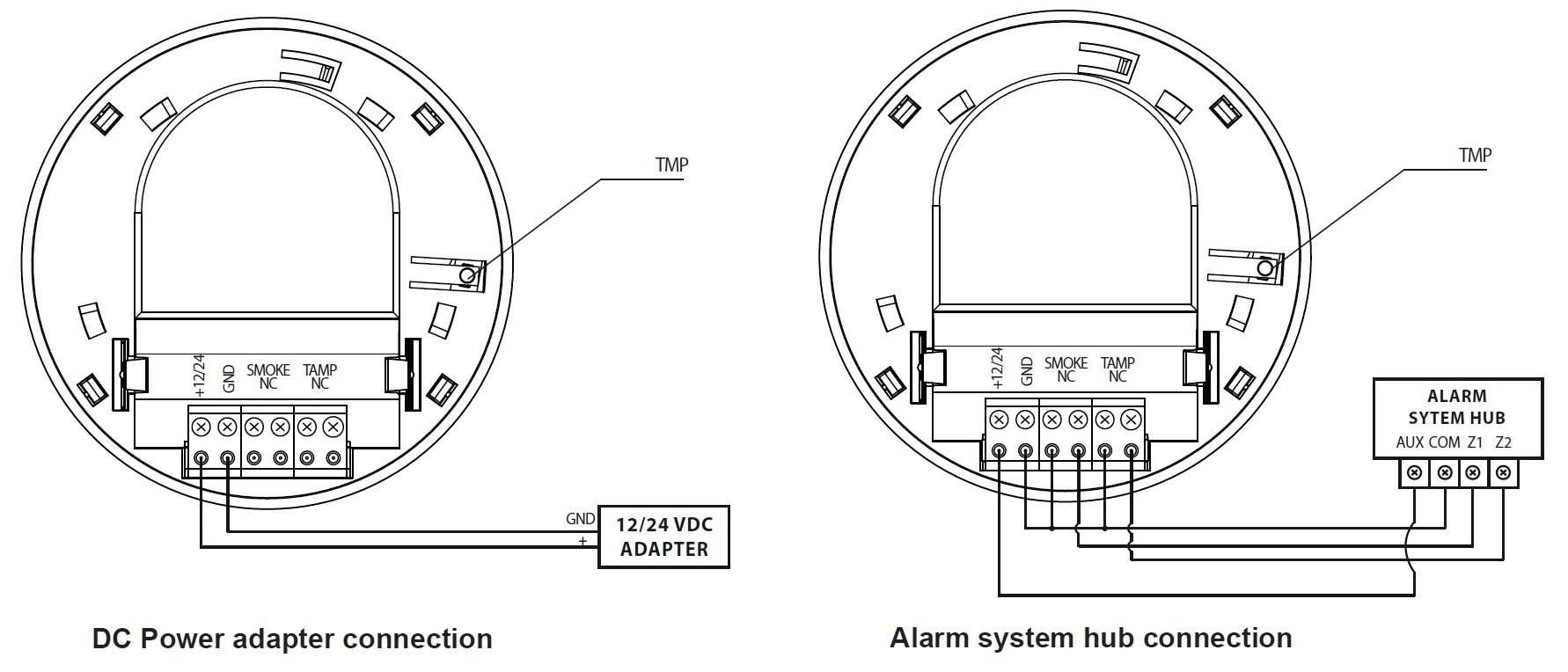
There are two powering modes for the Fibaro Smoke Sensor. By default it"s powered by a factory included battery. Alternatively it can work with a constant current, after connecting a 12 / 24 VDC power supply to +12/24 and GND terminals (see diagram no.3). Powering mode configuration is carried out automatically, while sensor is being included into the Z-Wave network. When battery powered, a Fibaro Smoke Sensor communicates with the Z-Wave network main controller periodically. Detected alarms are sent immediately, but configuration parameters and associations settings only at specified wake up intervals, or at a manual wake up (B-button triple click). In DC powering mode, configuration and associations parameters are sent when necessary, and in addition sensor serves as a Z-Wave signal repeater.
Switching to a constant current powering mode:
- Exclude a sensor from the Z-Wave network.
- Disconnect the battery.
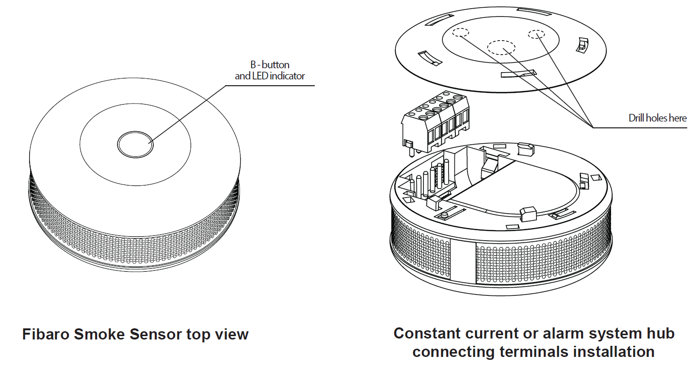
- Install the constant power connecting terminal, observing the diagram 2.
- Connect a constant current power source (12 / 24 VDC) to +12 and GND terminals observing wiring diagram 1.
- Include Fibaro Smoke Sensor into the Z-Wave network.
Installation:
- Include the device into the Z-Wave network (see p.I). Note the inclusion process may be performed ONLY in direct range of the main controller.
- If the sensor is to be VDC powered, drill holes in sensor"s holder. Note the sensor may be connected to a wired alarm system controller or fire prevention system.
- Install the sensor"s holder in desired location.
- If the sensor is to be VDC powered, connect wires observing diagram 3.
- If the sensor is to be connected to an alarm system or fire prevention system, connect it observing to diagram 4.
Product Usage
SMOKE DETECTION
Fibaro Smoke Sensor responds to physical presence of smoke. Smoke presence is required for the device to react. Fibaro Smoke Sensor performs a self test each 5 seconds and checks for smoke presence. Having detected smoke presence, the sensor checks 3 more times, at 1 second interval, whether the smoke is actually present. Once the smoke presence is confirmed, Fibaro Smoke Sensor triggers an alarm.
Smoke alarm is signaled by sending an appropriate alarm frame to devices and the Z-Wave controller, opening NC contact, and also by a constant sound signal and LED diode blinking red. Once the smoke alarm has ceased, the sensor checks 3 times, at 1 second interval, whether the smoke has actually disappeared before getting back to normal operation, i.e. performing a self test each 5 seconds and checking for smoke presence.
There are 3 sensitivity levels of the optical smoke detector used in Fibaro Smoke Sensor. By default, the detector is set to the middle sensitivity level. Sensitivity level depends on the parameter 82 settings.
DETECTING FIRE THROUGH TEMPERATURE ALARM
Apart from detecting smoke presence, Fibaro Smoke Sensor can detect fire by recording a rapid temperature rise. Temperature alarm threshold is user defined (parameter 81). Temperature alarm is signaled by the LED signaling diode blinking red and an intermittent sound signal.
| Reset to factory default | Fibaro Smoke Sensor reset erases the EPROM memory, including all information on the Z-Wave network and the main controller. Resetting Fibaro Smoke Sensor:
Successful reset will be confirmed with the LED changing colour to red and fading. At the same time, short signal will sound, same as at the power connection. |
| Inclusion | To include the device into the network, turn the controller into the inclusion mode and then triple click the B-button. Further you can use the auto-inclusion mode by setting the controller into the inclusion mode and then connect the constant current voltage supply. Auto-inclusion only works in constant current mode. |
| Exclusion | To include the device into the network, turn the controller into the inclusion mode and then triple click the B-button. Further you can use the auto-inclusion mode by setting the controller into the inclusion mode and then connect the constant current voltage supply. Auto-inclusion only works in constant current mode. |
| NIF | Hitting the B-button three times will send out a Node Information Frame. |
| Wakeup | When in battery mode tripple click on the B-button to wake up the device. |
| Protection | XXXProtection |
| FirmwareUpdate | XXXFirmwareUpdate |
| SetAssociation | XXXSetAssociation |
Association Groups:
| Group Number | Maximum Nodes | Description |
|---|---|---|
| 1 | 5 | assigned to the device status - sending the BASIC SET (default) or ALARM control frame to the associated devices having detected fire. |
| 2 | 5 | assigned to a TMP button and the malfunction alarm. Alarm frame will be sent to the associated devices once tampering or malfunction are detected. |
| 3 | 1 | reports the device status and allows for assigning single device only (the main controller by default - the device reports its status to the main controller). |
Configuration Parameters
Parameter 1: Smoke alarm cancellation delay
time period, during which the Smoke Sensor will keep indicating the smoke alarm after smoke will have disappeared Size: 2 Byte, Default Value: 0000
| Setting | Description |
|---|---|
| 0000 | no delay, immediate cancellation |
| 0001 - 4380 | delay |
| 8000 | alarm cancellation inactive - Smoke Sensor will keep indicating smoke alarm after the smoke will have disappeared. The smoke alarm can be only ceased manually, by entering 2nd menu level |
Parameter 2: LED indicator and acoustic alarm turned ON / OFF at any alarm type
activates/deactivates the LED indicator and acoustic alarm for any alarm type. Doesnu2019t affect the Z-Wave alarm. Size: 1 Byte, Default Value: 03
| Setting | Description |
|---|---|
| 00 | acoustic and visual alarms inactive |
| 01 | acoustic alarm inactive, visual alarm active |
| 02 | acoustic alarm active, visual alarm inactive |
| 03 | acoustic and visual alarms active |
Parameter 5: Type of alarm frame sent to 1-st Association Group devices (smoke alarm)
choose a command class used in 1-st Association Group Size: 1 Byte, Default Value: ff
| Setting | Description |
|---|---|
| 00 | ALARM SENSOR (SMOKE) command frame |
| ff | BASIC_SET command frame |
Parameter 7: Forced dimming level sent to 1-st association group devices
Forced level of dimming / opening dimmers, roller blinds etc. devices at sending turn on / open / change level commands to 1-st Association Groupu2019s devices. Size: 1 Byte, Default Value: 7f
| Setting | Description |
|---|
Parameter 10: Temperature report interval
Time interval between consecutive temperature reports Size: 2 Byte, Default Value: 0000
| Setting | Description |
|---|
Parameter 12: Temperature report hysteresis
temperature change, resulting in a temperature report Size: 1 Byte, Default Value: 14
| Setting | Description |
|---|
Parameter 13: Alarm broadcast
defines the broadcast alarm setting (alarm to all devices in direct range) Size: 1 Byte, Default Value: 00
| Setting | Description |
|---|---|
| 00 | broadcast inactive |
| 01 | smoke alarm broadcast (1-st Association Group) active; tamper alarm broadcast (2-nd Association Group) inactive |
| 02 | smoke alarm broadcast (1-st Association Group) inactive; tamper alarm broadcast (2-nd Association Group) active |
| 03 | smoke alarm broadcast active (1-st association group); tamper alarm broadcast (2-nd association group) active |
Parameter 73: Temperature measurement compensation
temperature value to be added to or deducted from the current measured temperature Size: 2 Byte, Default Value: 0000
| Setting | Description |
|---|
Parameter 80: Z-Wave range test interval
Time period between the consecutive Z-Wave network range tests Size: 1 Byte, Default Value: 01
| Setting | Description |
|---|
Parameter 81: Temperature alarm threshold
Temperature value, above which the temperature alarm is sent Size: 1 Byte, Default Value: 36
| Setting | Description |
|---|---|
| 00 | 0 - temperature alarm inactive |
Parameter 82: Smoke Sensor sensitivity
There are 3 levels of sensitivity to smoke presence. Level 1 means the highest sensitivity. Size: 1 Byte, Default Value: 02
| Setting | Description |
|---|---|
| 01 | HIGH Sensitivity |
| 02 | MEDIUM Sensitivity |
| 03 | LOW Sensitivity |
Parameter 83: Black Box sensitivity level
Parameter specifies temperature and smoke level after which the Black Box starts recording them Size: 1 Byte, Default Value: 00
| Setting | Description |
|---|---|
| 01 | HIGH Sensitivity |
| 02 | MEDIUM Sensitivity |
| 03 | LOW Sensitivity |
Parameter 84: Malfunction alarm
Time interval in which malfuntion alarm, if detected, is repeated using visual and acoustic alarms. Size: 1 Byte, Default Value: 0a
| Setting | Description |
|---|
Parameter 85: Temperature alarm
Time interval in which temperature alarm, if detected, is repeated using visual and acoustic alarms. Size: 1 Byte, Default Value: 05
| Setting | Description |
|---|
Parameter 86: Lack of the Z-Wave range alarm
Time interval in which lack of the Z-Wave network alarm, if detected, is repeated using visual and acoustic alarms. Size: 2 Byte, Default Value: 0168
| Setting | Description |
|---|
Parameter 87: Low battery alarm
Time interval in which low battery alarm, if detected, is repeated using visual and acoustic alarms. Size: 2 Byte, Default Value: 0168
| Setting | Description |
|---|
Parameter 88: temperature measurement compensation for report
Consider temperature measurement compensation (parameter 73) when sending temperature report. Size: 1 Byte, Default Value: 00
| Setting | Description |
|---|---|
| 00 | 0 - ignore temperature compensation |
| 01 | 1 - include temperature compensation |
Parameter 89: Tamper alarm
activates/inactivates temper switch alarm Size: 1 Byte, Default Value: 01
| Setting | Description |
|---|---|
| 00 | 0 - tamper alarm inactive |
| 01 | 1 - tamper alarm active, with cancellation option available |
| 02 | 2 - tamper alarm active, without cancellation option |
Technical Data
| Dimensions | 0.0650000x0.0650000x0.0280000 mm |
| Weight | 43 gr |
| Hardware Platform | ZM3102 |
| EAN | 5902020528241 |
| Battery Type | 1 * CR123 |
| Firmware Version | 02.01 |
| Z-Wave Version | 03.34 |
| Certification ID | ZC08-14060003 |
| Z-Wave Product Id | 010f.0c00.1000 |
| Frequency | Europe - 868,4 Mhz |
| Maximum transmission power | 5 mW |