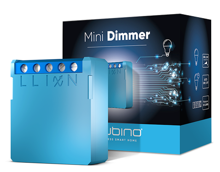
Qubino (Goap)
Mini Dimmer
SKU: GOAEZMNHHD1


Quickstart
This is a
1. Enable add/remove mode on your Z-Wave gateway (hub)
2. Automatic selection of secure/unsecure inclusion.
3. The device can be automatically added to a Z-Wave network during the first 2 minutes
4. Connect the device to the power supply
5. Auto-inclusion will be initiated within 5 seconds of connection to the power supply and the device will automatically enroll in your network. (when the device is excluded and connected to the power supply it automatically enters the LEARN MODE state.)
NOTE: LEARN MODE state allows the device to receive network infromation from the controller
NOTE: Please wait at least 30 seconds between each inclusion and exclusion.
Important safety information
Please read this manual carefully. Failure to follow the recommendations in this manual may be dangerous or may violate the law. The manufacturer, importer, distributor and seller shall not be liable for any loss or damage resulting from failure to comply with the instructions in this manual or any other material. Use this equipment only for its intended purpose. Follow the disposal instructions. Do not dispose of electronic equipment or batteries in a fire or near open heat sources.What is Z-Wave?
Z-Wave is the international wireless protocol for communication in the Smart Home. This device is suited for use in the region mentioned in the Quickstart section.
Z-Wave ensures a reliable communication by reconfirming every message (two-way communication) and every mains powered node can act as a repeater for other nodes (meshed network) in case the receiver is not in direct wireless range of the transmitter.
This device and every other certified Z-Wave device can be used together with any other certified Z-Wave device regardless of brand and origin as long as both are suited for the same frequency range.
If a device supports secure communication it will communicate with other devices secure as long as this device provides the same or a higher level of security. Otherwise it will automatically turn into a lower level of security to maintain backward compatibility.
For more information about Z-Wave technology, devices, white papers etc. please refer to www.z-wave.info.
Product Description
Mini Dimmer is a MOSFET-switching light device that also supports control of low-voltage halogen lamps with electronic transformers, dimmable compact fluorescent lights, and dimmable LED bulbs. It measures the power consumption of the connected device. It supports push-button/momentary switches (default) and toggle switches. It can work with or without the neutral line. Qubino Mini Dimmer allows the easiest and quickest installation. It is designed to be mounted inside a flush mounting box, hidden behind a traditional wall switch. It acts as a repeater in order to improve the range and stability of the Z-Wave network.
Prepare for Installation / Reset
Please read the user manual before installing the product.
In order to include (add) a Z-Wave device to a network it must be in factory default state. Please make sure to reset the device into factory default. You can do this by performing an Exclusion operation as described below in the manual. Every Z-Wave controller is able to perform this operation however it is recommended to use the primary controller of the previous network to make sure the very device is excluded properly from this network.
Reset to factory default
This device also allows to be reset without any involvement of a Z-Wave controller. This procedure should only be used when the primary controller is inoperable.
1. Connect the device to the power supply
2. Within the first minute, the device is connected to the power supply, toggle the switch connected to the I1 terminal 5 times within 3 seconds. The reset with a switch connected to I1 is possible only in the first minute after the device is connected to the power or Press and hold the S (Service) button for at least 6 seconds if connected to 24-30VDC
NOTE: By resetting the device, all custom parameters previously set on the device will return to their default values, and the owner ID will be deleted. Use this reset procedure only when the main gateway (hub) is missing or otherwise inoperable. After the reset is successfully done the autocalibration will trigger and the green LED will start blinking.
Safety Warning for Mains Powered Devices
ATTENTION: only authorized technicians under consideration of the country-specific installation guidelines/norms may do works with mains power. Prior to the assembly of the product, the voltage network has to be switched off and ensured against re-switching.
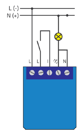
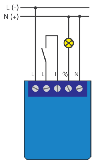
Installation
2 - Wire System
3 - Wire System
Inclusion/Exclusion
On factory default the device does not belong to any Z-Wave network. The device needs to be added to an existing wireless network to communicate with the devices of this network. This process is called Inclusion.
Devices can also be removed from a network. This process is called Exclusion. Both processes are initiated by the primary controller of the Z-Wave network. This controller is turned into exclusion respective inclusion mode. Inclusion and Exclusion is then performed doing a special manual action right on the device.
Inclusion
1. Connect the device to the power supply2. Enable add/remove mode on your Z-Wave gateway (hub)
3. Toggle the switch connected to the I1 terminal 3 times within 3 seconds (this procedure put the device in LEARN MODE)ORPress and hold the S (Service) button between 2 and 6 seconds if connected to 24-30VDC (this procedure put the device in LEARN MODE)
4. A new device will appear on your dashboard
NOTE: LEARN MODE state allows the device to receive network infromation from the conttoller
NOTE: Please wait at least 30 seconds between each inclusion and exclusion.Mini Dimmer supports the latest Security 2 feature. When adding the Mini Dimmer to a Z-Wave network with a controller supporting Security 2 (S2), the PIN code of the Z-Wave Device Specific Key (DSK) is required. The unique DSK code is printed on the product label and a copy is inserted in the packaging, which must not be lost. Do not remove the DSK from the product. As a backup measure, use the label in the packaging. The first five digits of the key are highlighted or underlined to help the user identify the PIN code portion of the DSK text.
Exclusion
1. Connect the device to the power supply2. Make sure the device is within direct range of your Z-Wave gateway (hub) or use a hand-held Z-Wave remote to perform exclusion
3. Enable add/remove mode on your Z-Wave gateway (hub)
4. Toggle the switch connected to the I1 terminal 3 times within 3 seconds (this procedure put the device in LEARN MODE) OR Press and hold the S (Service) button between 2 and 6 seconds if connected to 24-30VDC (this procedure put the device in LEARN MODE)
5. The device will be removed from your network, but any custom configuration parameters will not be erased
NOTE: LEARN MODE state allows the device to receive network information from the controller
NOTE: Please wait at least 30 seconds between each inclusion and exclusion.
Auto-Inclusion
Beside the standard inclusion this devices supports the so called auto inclusion. Right after powering up the device remains in inclusion state and can be included by (any) gateway without further actions on the device itself. The auto inclusion mode will time out after some time.Product Usage
When the Mini Dimmer is included:
Quick trouble shooting
Here are a few hints for network installation if things dont work as expected.
- Make sure a device is in factory reset state before including. In doubt exclude before include.
- If inclusion still fails, check if both devices use the same frequency.
- Remove all dead devices from associations. Otherwise you will see severe delays.
- Never use sleeping battery devices without a central controller.
- Dont poll FLIRS devices.
- Make sure to have enough mains powered device to benefit from the meshing
Association - one device controls an other device
Z-Wave devices control other Z-Wave devices. The relationship between one device controlling another device is called association. In order to control a different device, the controlling device needs to maintain a list of devices that will receive controlling commands. These lists are called association groups and they are always related to certain events (e.g. button pressed, sensor triggers, ...). In case the event happens all devices stored in the respective association group will receive the same wireless command wireless command, typically a 'Basic Set' Command.
Association Groups:
| Group Number | Maximum Nodes | Description |
|---|---|---|
| 1 | 1 | Z-Wave Plus Lifeline |
| 2 | 16 | Basic On/Off |
| 3 | 16 | StartStop level change |
| 4 | 16 | Multilevel set |
Configuration Parameters
Z-Wave products are supposed to work out of the box after inclusion, however certain configuration can adapt the function better to user needs or unlock further enhanced features.
IMPORTANT: Controllers may only allow configuring signed values. In order to set values in the range 128 ... 255 the value sent in the application shall be the desired value minus 256. For example: To set a parameter to 200 it may be needed to set a value of 200 minus 256 = minus 56. In case of a two byte value the same logic applies: Values greater than 32768 may needed to be given as negative values too.
Parameter 1: In-wall Switch Type for Load to control I1
With this parameter, you can select between push-button (momentary) and on/off toggle switch types. Size: 1 Byte, Default Value: 0
| Setting | Description |
|---|---|
| 0 | push-button (momentary) |
| 1 | on/off toggle switch |
Parameter 5: Working mode
With this parameter, you can change the device presentation on the user interface. NOTE: After parameter change, first exclude the device (without setting parameters to default value) then wait at least 30s before reinclusion. Size: 1 Byte, Default Value: 0
| Setting | Description |
|---|---|
| 0 | Dimmer mode |
| 1 | Switch mode (works only in 3 way wiring-connection with neutral line) |
Parameter 11: Turn Load 1 Off Automatically with Timer
If Load is ON, you can schedule it to turn OFF automatically after a period of time defined in this parameter. The timer is reset to zero each time the device receives an ON or OFF command, either remotely (from the gateway (hub) or associated device) or locally from the switch. Size: 2 Byte, Default Value: 0
| Setting | Description |
|---|---|
| 0 | Auto OFF Disabled |
| 1 - 32536 | 1 - 32536 seconds - Auto OFF timer enabled for a given amount of seconds |
Parameter 12: Turn Load 1 On Automatically with Timer
If Load is OFF, you can schedule it to turn ON automatically after a period of time defined in this parameter. The timer is reset to zero each time the device receives an OFF or ON command, either remotely (from the gateway (hub) or associated device) or locally from the switch. Size: 2 Byte, Default Value: 0
| Setting | Description |
|---|---|
| 0 | Auto ON Disabled |
| 1 - 32536 | 1 - 32536 seconds - Auto ON timer enabled for a given amount of seconds |
Parameter 21: Enable/Disable the Double click function
If the Double click function is enabled, a fast double click on the push-button will set the dimming level to the maximum dimming value. Size: 1 Byte, Default Value: 0
| Setting | Description |
|---|---|
| 0 | double click disabled |
| 1 | double click enabled |
Parameter 30: Restore on/off status for load after power failure
This parameter determines if on/off status is saved and restored for the load after power failure. Size: 1 Byte, Default Value: 0
| Setting | Description |
|---|---|
| 0 | Device saves last on/off status and restores it after a power failure. |
| 1 | Device does not save on/off status and does not restore it after a power failure, it remains off. |
Parameter 40: Watt Power Consumption Reporting Threshold for Load
Choose by how much the power consumption needs to increase or decrease to be reported. Values correspond to percentages so if 10 is set (by default), the device will report any power consumption changes of 10% or more compared to the last reading. NOTE: The power consumption needs to increase or decrease by at least 2 Watts to be reported, regardless of percentage set in this parameter. Size: 1 Byte, Default Value: 10
| Setting | Description |
|---|---|
| 0 | Power consumption reporting disabled |
| 1 - 100 | 1% - 100% Power consumption reporting enabled. New value is reported only when Wattage in real time changes by more than the percentage value set in this parameter compared to the previous Wattage reading, starting at 1% (the lowest value possible). |
Parameter 42: Watt Power Consumption Reporting Time Threshold for Load
Set value refers to the time interval with which power consumption in Watts is reported (032767 seconds). If 300 is entered, energy consumption reports will be sent to the gateway (hub) every 300 seconds (or 5 minutes) if there was a change compared from the last report.NOTE: Values from 1 to 29 are ignored by device due to standard recommendation.NOTE: The report will be send only if there was a change compared to the last report. Size: 2 Byte, Default Value: 0
| Setting | Description |
|---|---|
| 0 | Power consumption reporting on time interval disabled |
| 30 - 32767 | 30 - 32767seconds. Power consumption reporting enabled. Report is sent according to time interval (value) set here. |
Parameter 60: Minimum dimming value
The value set in this parameter determines the minimum dimming value (the lowest value which can be set on the device, when, for example, dimming lights with wall switch or slider in the GUI (Gateway - hub)) (Data type 1 byte dec) default value 0 = 0% (minimum dimming value) 0- 98 = 0% - 98%, step is 1%. Minimum dimming value is set by entering a value. NOTE: The minimum level may not be higher than the maximum level! Size: 1 Byte, Default Value: 0
| Setting | Description |
|---|---|
| 0 - 98 | 0% - 98%, step is 1%. Minimum dimming value is set by entering a value |
Parameter 61: Maximum dimming value
The value set in this parameter determines the maximum dimming value (the highest value which can be set on the device, when, for example, dimming lights with wall switch or slider in the GUI (Gateway - hub)) NOTE: The maximum level may not be lower than the minimum level! Size: 1 Byte, Default Value: 99
| Setting | Description |
|---|---|
| 1 - 99 | 1% - 99%, step is 1%. Maximum dimming value is set by entering a value. |
Parameter 65: Dimming time when key pressed (soft on/off)
Choose the time during which the device will move between the min. and max. dimming values by a short press of the push-button I1. Size: 1 Byte, Default Value: 1
| Setting | Description |
|---|---|
| 1 - 127 | 1 seconds - 127 seconds, step is 1 second |
Parameter 66: Dimming time when key hold
Choose the time during which the Dimmer will move between the min. and max. dimming values during a continuous press of the push-button I1, by an associated device or through the UI controls (BasicSet, SwitchMultilevelSet). Size: 2 Byte, Default Value: 3
| Setting | Description |
|---|---|
| 1 - 127 | 1 - 127 seconds |
| 128 - 253 | 1 - 126 minutes |
Parameter 67: Ignore start level
Choose whether the device should use (or disregard) the start dimming level value. If the device is configured to use the start level, it should start the dimming process from the currently set dimming level. This parameter is used with association group 3.NOTE: Parameter is valid only in Dimmer mode. In Switch mode the parameter has no effect. Size: 1 Byte, Default Value: 0
| Setting | Description |
|---|---|
| 0 | use the start level value |
| 1 | ignore the start level value |
Parameter 68: Dimming duration
Choose the time during which the device will transition from the current value to the new target value. This parameter applies to the association group 3.NOTE: Parameter is valid only in Dimmer mode. In Switch mode the parameter has no effect. Size: 1 Byte, Default Value: 0
| Setting | Description |
|---|---|
| 0 | dimming duration according to parameter 66 |
| 1 - 127 | from 1 to 127 seconds |
Parameter 70: Overload safety switch
The function allows for turning off the controlled device in case of exceeding the defined power for more than 5s. Controlled device can be turned back on by input I1 or sending a control frame. NOTE: This functionality is not an overload safety protection, please check the technical specifications chapter for more details.In case of overload the following message will be send towards the controller: COMMAND_CLASS_NOTIFICATION_V5 The Alarm V1 type field set to 0x00 Notification Type 0x08 and 0x08 (Overload detected) Size: 2 Byte, Default Value: 200
| Setting | Description |
|---|---|
| 0 | Disable |
| 1 - 200 | 1 - 200 Watt |
Parameter 71: Calibration trigger
Choose when will be the calibration procedure triggered. Size: 1 Byte, Default Value: 0
| Setting | Description |
|---|---|
| 1 | calibration done after power cycle regardless of inclusion status |
| 2 | force calibration. Calibration will start immediately |
Parameter 72: Calibration status (read only)
With this parameter you can check the calibration status. Size: 1 Byte, Default Value: 2
| Setting | Description |
|---|---|
| 1 | calibration was successful |
| 2 | calibration failed |
Parameter 73: Alarm/Notification events
This parameter defines the module behaviour in case it receives any Alarm/Notification events.NOTE: When value 3 is selected the default time interval of the blinking is 10 minutes. It can be stopped with a button press or sending a control frame. To adjust the time interval please refer to parameter 74Alarm/Notification time interval. Size: 1 Byte, Default Value: 0
| Setting | Description |
|---|---|
| 1 | turn OFF |
| 2 | turn ON |
| 3 | start blinking (output turns 1s ON, and 1s OFF) |
Parameter 74: Alarm/Notification time interval (dependant on parameter 73)
This parameter defines the time interval of the blinking state, once the module receives an alarm/notification event. Minimum step increase is 1 minute.NOTE: This parameter does not have any effect if parameter 73 is not set to value 3. Size: 1 Byte, Default Value: 10
| Setting | Description |
|---|---|
| 1 - 125 | 1-125 minutes |
Technical Data
| Dimensions | 0.0330000x0.0380000x0.0155000 mm |
| Weight | 24 gr |
| Hardware Platform | ZM5101 |
| EAN | 3830062071673 |
| IP Class | IP 20 |
| Voltage | 230 V |
| Load | 200 W |
| Device Type | Light Dimmer Switch |
| Network Operation | Always On Slave |
| Z-Wave Version | 6.71.03 |
| Certification ID | ZC10-19056504 |
| Z-Wave Product Id | 0x0159.0x0001.0x0055 |
| Electric Load Type | Dimmable FluorescentDimmable LEDFluorescentIncandescentLED |
| Switch Type | Push Button |
| Supported Notification Types | Power Management |
| Color | Blue |
| Communications Protocol | Z-Wave Serial API |
| Outdoor Use | ok |
| Supported Meter Type | Electric Energy |
| Neutral Wire Required | ok |
| Frequency | Europe - 868,4 Mhz |
| Maximum transmission power | 5 mW |
Supported Command Classes
- Association Grp Info V2
- Association V2
- Basic
- Configuration
- Device Reset Locally
- Manufacturer Specific V2
- Meter V4
- Notification V5
- Powerlevel
- Security
- Security 2
- Supervision
- Switch Multilevel V3
- Transport Service V2
- Version V2
- Zwaveplus Info V2
Controlled Command Classes
- Basic
- Switch Multilevel V3
Explanation of Z-Wave specific terms
- Controller — is a Z-Wave device with capabilities to manage the network. Controllers are typically Gateways,Remote Controls or battery operated wall controllers.
- Slave — is a Z-Wave device without capabilities to manage the network. Slaves can be sensors, actuators and even remote controls.
- Primary Controller — is the central organizer of the network. It must be a controller. There can be only one primary controller in a Z-Wave network.
- Inclusion — is the process of adding new Z-Wave devices into a network.
- Exclusion — is the process of removing Z-Wave devices from the network.
- Association — is a control relationship between a controlling device and a controlled device.
- Wakeup Notification — is a special wireless message issued by a Z-Wave device to announces that is able to communicate.
- Node Information Frame — is a special wireless message issued by a Z-Wave device to announce its capabilities and functions.