Qubino
Flush 1D relay
SKU: GOAEZMNHND1


Quickstart
This is a
Press service button S for more than 2 second or
Press push button I1 three times within 3s (3 times change switch state within 3 seconds).
Important safety information
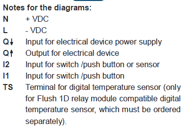
Please read this manual carefully. Failure to follow the recommendations in this manual may be dangerous or may violate the law. The manufacturer, importer, distributor and seller shall not be liable for any loss or damage resulting from failure to comply with the instructions in this manual or any other material. Use this equipment only for its intended purpose. Follow the disposal instructions. Do not dispose of electronic equipment or batteries in a fire or near open heat sources.Product Description
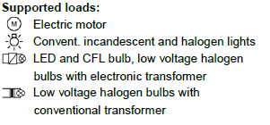
Qubino Flush 1D relay with voltage free (dry contact) output contact.
This Z-Wave module is used for switching on or off the electrical device (e.g. light, fan, etc ...). The module can be controlled either through Z-wave network or through the wall switch.
The module is designed to be mounted inside a “flush mounting box”, hidden behind a traditional wall switch.
Module supports connection of digital temperature sensor. It is designed to act as repeater in order to improve range and stability of Z-wave network.
Output contact is voltage free (dry contact), so also loads with different power supply can be connected to the module.
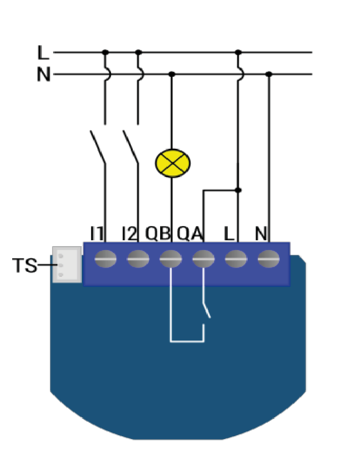
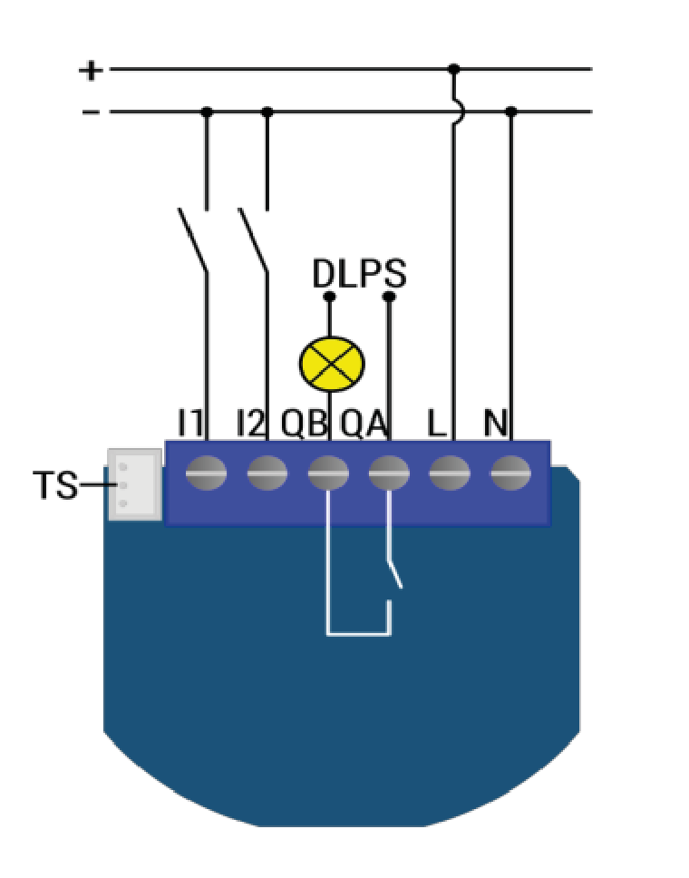
Installation
Electrical diagram 230VAC
Option for different load power supply - DPLS:
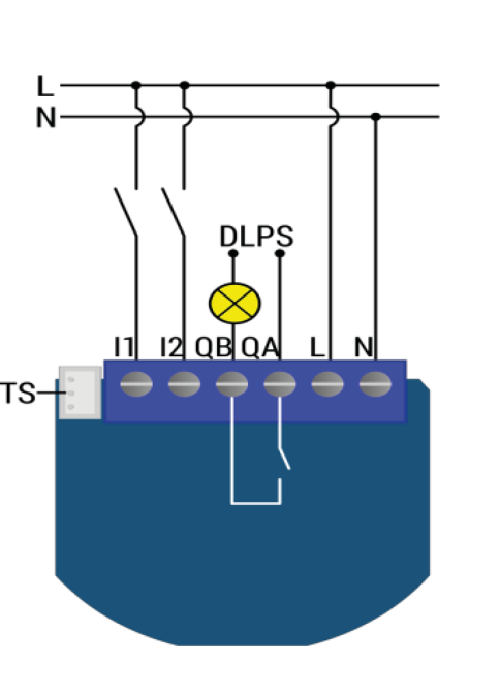
Electrical diagram 24VDC
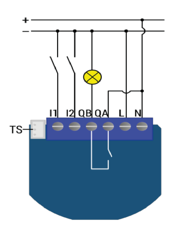
Option for different load power supply - DPLS:
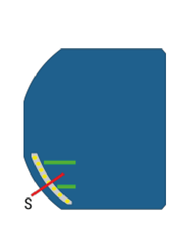 Service button (used to add or remove module from the Z-Wave network in case of 24 V SELV power supply).
Product Usage
| Reset to factory default | If the service button S is pressed for more than 6 seconds the module will be reset to the factory defoult state. |
| Inclusion | Press service button S for more than 2 second or Press push button I1 three times within 3s (3 times change switch state within 3 seconds). |
| Exclusion | Press service button S for more than 6 second or Press push button I1 five times within 3s (5 times change switch state within 3 seconds) in the first 60 seconds after the module is connected to the power supply. |
| NIF | XXXNIF |
| Wakeup | XXXWakeupDescription |
| Protection | XXXProtection |
| FirmwareUpdate | XXXFirmwareUpdate |
| SetAssociation | XXXSetAssociation |
Association Groups:
| Group Number | Maximum Nodes | Description |
|---|---|---|
| 1 | 1 | Lifeline group (reserved for communication with the main controller), 1 node allowed. |
| 2 | 16 | basic on/off (triggered at change of the output state and reflecting its state) up to 16 nodes. |
| 3 | 16 | basic on/off (triggered at change of the input I2 state and reflecting its state) up to 16 nodes. |
| 4 | 16 | Binary Sensor Report (triggered at change of the input I2 state and reflecting its state) up to 16 nodes. |
| 5 | 16 | Notification Report (triggered at change of the input I2 state and reflecting its state) up to 16 nodes. |
| 6 | 16 | multilevel sensor report (triggered at change of temperature sensor) |
Configuration Parameters
Parameter 1: Input 1 switch type
Defines the type of switch connected to Input 1 Size: 1 Byte, Default Value: 1
| Setting | Description |
|---|---|
| 0 | mono-stable switch type (push button) |
| 1 | bi-stable switch type |
Parameter 2: Input 2 contact type
Defines the type of switch connected to Input 2 Size: 1 Byte, Default Value: 0
| Setting | Description |
|---|---|
| 0 | NO (normally open) input type |
| 1 | NC (normally close) input type |
Parameter 10: Activate / deactivate functions ALL ON/ALL OFF
Support to activate / deactivate functions ALL ON/ALL OFFFlush 1D relay module responds to commands ALL ON / ALL OFF that may be sent by the main controller or by other controller belonging to the system. Size: 2 Byte, Default Value: 255
| Setting | Description |
|---|---|
| 0 | ALL ON is not active ALL OFF is not active |
| 1 | ALL ON is not active ALL OFF active |
| 2 | ALL ON active ALL OFF is not active |
| 255 | ALL ON active, ALL OFF active |
Parameter 11: Automatic turning off output after set time
Support automatic turning off output after set time.When relay is ON it goes automatically OFF after time defined by this parameter. Timer is reset to zero each time the module receive ON command regardless from where it comes (push button, associated module, controller,..). Size: 2 Byte, Default Value: 0
| Setting | Description |
|---|---|
| 0 | Auto OFF disabled |
| 1 - 32535 | 1 - 32535 = 1second (0,01s) - 32535 seconds (325,35s) Auto OFF enabled with define time, step is 1s or 10ms according to parameter nr.15 |
Parameter 12: Automatic turning on output after set time
Support automatic turning on output after set time When relay is OFF it goes automatically ON after time defined by this parameter. Timer is reset to zero each time the module receive OFF command regardless from where it comes (push button, associated module, controller,..). Size: 2 Byte, Default Value: 0
| Setting | Description |
|---|---|
| 0 | Auto ON disabled |
| 1 - 32535 | 1 - 32535 = 1second (0,01s) - 32536 seconds (325,35s) Auto ON enabled with define time, step is 1s or 10ms according to parameter nr.15 |
Parameter 15: Automatic turning off / on seconds or milliseconds selection
Support automatic turning off / on seconds or milliseconds selectionNOTE: This parameter is valid for both, turning on and turning off parameters. Size: 1 Byte, Default Value: 0
| Setting | Description |
|---|---|
| 0 | seconds selected |
| 1 | milliseconds selected |
Parameter 30: Saving the state of the relay after a power failure
Support saving the state of the relay after a power failure Size: 1 Byte, Default Value: 0
| Setting | Description |
|---|---|
| 0 | Flush 1D relay module saves its state before power failure (it returns to the last position saved before a power failure) |
| 1 | Flush 1D relay module does not save the state after a power failure, it returns to "off" position. |
Parameter 63: Output Switch selection
Support output Switch selectionSet value means the type of the device that is connected to the output. The device type can be normally open (NO) or normally close (NC). Size: 1 Byte, Default Value: 0
| Setting | Description |
|---|---|
| 0 | When system is turned off the output is 0V (NC). |
| 1 | When system is turned off the output is 230V or 24V (NO). |
Parameter 100: Enable / Disable Endpoint I2 or select Notification Type and Event
Support Enable / Disable Endpoint I2 or select Notification Type and EventEnabling I2, means that Endpoint (I2) will be present on UI. Disabling it will result in hiding the endpoint according to the parameter set value. Additionally, a Notification Type and Event can be selected for the endpoint. NOTE: After parameter change module has to be reincluded into the network for the setting to take effect! Size: 1 Byte, Default Value: 1
| Setting | Description |
|---|---|
| 0 | Endpoint, I2 disabled |
| 1 | Home Security; Motion Detection, unknown location |
| 2 | Carbon Monoxide; Carbon Monoxide detected, unknown location. |
| 3 | Carbon Dioxide; Carbon Dioxide detected, unknown location. |
| 4 | Water Alarm; Water Leak detected, unknown location. |
| 5 | Heat Alarm; Overheat detected, unknown location. |
| 6 | Smoke Alarm; Smoke detected, unknown location. |
Parameter 110: Temperature sensor offset settings
Defines temperature sensor offset settingsSet value is added or subtracted to actual measured value by sensor. Size: 2 Byte, Default Value: 32536
| Setting | Description |
|---|---|
| 1 - 100 | value from 0.1C to 10.0C is added to actual measured temperature. |
| 1001 - 1100 | value from -0.1C to -10.0C is subtracted to actual measured temperature. |
| 32536 | offset is 0.0C |
Parameter 120: Digital temperature sensor reporting
Defines the digital temperature sensor reportingIf digital temperature sensor is connected, module reports measured temperature on temperature change defined by this parameter. Size: 1 Byte, Default Value: 5
| Setting | Description |
|---|---|
| 0 | Reporting disabled |
| 1 - 127 | 0,1C - 12,7C, step is 0,1C |
Technical Data
| Dimensions | 41x36x15 mm |
| Weight | 27 gr |
| Hardware Platform | ZM5202 |
| EAN | 3830062070072 |
| IP Class | IP 20 |
| Voltage | 230 V |
| Load | 2300 W |
| Device Type | On/Off Power Switch |
| Network Operation | Always On Slave |
| Z-Wave Version | 6.51.06 |
| Certification ID | ZC10-15070017 |
| Z-Wave Product Id | 0x0159.0x0002.0x0053 |
| Frequency | Europe - 868,4 Mhz |
| Maximum transmission power | 5 mW |