Qubino
Flush Shutter DC
SKU: GOAEZMNHOD1

Quickstart
This is a
Important safety information
Please read this manual carefully. Failure to follow the recommendations in this manual may be dangerous or may violate the law. The manufacturer, importer, distributor and seller shall not be liable for any loss or damage resulting from failure to comply with the instructions in this manual or any other material. Use this equipment only for its intended purpose. Follow the disposal instructions. Do not dispose of electronic equipment or batteries in a fire or near open heat sources.Product Description
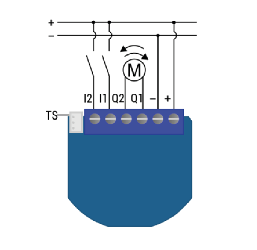
Installation
Electrical diagram 12 - 24VDC
Product Usage
Shutter positioning calibration
There are two procedures of calibration.
Calibration through the inputs I1 and I2
Clicking push-button (for time < full turn slates time-par.72) connected to I1 (up), initiates Shutter up movement.
Keeping pressed push-button (for time > full turn slates time-par.72) connected to I1 (up), initiates Shutter up movement, until the push-button is released.
| Reset to factory default | Press service button S for more than 6 second or
Press push button I1 five times within 3s (5 times change switch state within 3 seconds) in the first 60 seconds after the module is connected to the power supply |
| Inclusion | Press service button S for more than 2 second or
Press push button I1 three times within 3s (3 times change switch state within 3 seconds). |
| Exclusion | Press service button S for more than 6 second or
Press push button I1 five times within 3s (5 times change switch state within 3 seconds) in the first 60 seconds after the module is connected to the power supply |
| NIF | XXXNIF |
| Wakeup | XXXWakeupDescription |
| Protection | XXXProtection |
| FirmwareUpdate | XXXFirmwareUpdate |
| SetAssociation | XXXSetAssociation |
Association Groups:
| Group Number | Maximum Nodes | Description |
|---|---|---|
| 1 | 1 | default reporting group (reserved for the main controller) |
| 2 | 16 | basic on/off (triggered at change of the input I1 state and reflecting its state) |
| 3 | 16 | basic on/off (triggered at change of the input I2 state and reflecting its state) |
| 4 | 16 | basic on/off (triggered at sensing moving direction of roller: up=255, down=0) |
| 5 | 16 | basic on/off (triggered at reaching roller position: bottom=255, top=0) |
| 6 | 16 | basic on/off (triggered at reaching roller position: bottom=255, not bottom=0) |
| 7 | 16 | multilevel set (triggered at changes of value of the Flush Shutter DC position) |
| 8 | 16 | multilevel set (triggered at changes of value of slats tilting position) |
| 9 | 16 | multilevel sensor report (triggered at change of temperature sensor) |
Configuration Parameters
Parameter 10: Activate/deactivate functions ALL ON / ALL OFF
Flush Shutter responds to commands ALL ON / ALL OFF that may be sent by the main controller or by other controllers belonging to the system. Size: 2 Byte, Default Value: 255
| Setting | Description |
|---|---|
| 0 | ALL ON is not active ALL OFF is not active |
| 1 | ALL ON is not active ALL OFF active |
| 2 | ALL ON active ALL OFF is not active |
| 255 | ALL ON active, ALL OFF active. |
Parameter 40: Power reporting in Watts on power change for Q1 or Q2
Set value means percentage, set value from 0 – 100 = 0% - 100%.
NOTE: if power changed is less than 1W, the report is not send (pushed), independent of percentage set.
Size: 1 Byte, Default Value: 1
| Setting | Description |
|---|---|
| 0 | reporting disabled |
| 1 - 100 | 1% - 100% Reporting enabled. Power report is send (push) only when actual power (in Watts) in real time changes for more than set percentage comparing to previous actual power in Watts, step is 1%. |
Parameter 42: Power reporting in Watts by time interval for Q1 or Q2
Set value means time interval (0 – 32767) in seconds, when power report is send. Size: 2 Byte, Default Value: 300
| Setting | Description |
|---|---|
| 0 | reporting disabled |
| 1 - 32767 | 1 second - 32767 seconds. Reporting enabled, power report is send with time interval set by entered value. |
Parameter 71: Operating modes
This parameter defines selection between two available operating modesNOTE: After parameter change, first exclude module (without setting parameters to default value) then wait at least 30s and then re include the module! Size: 1 Byte, Default Value: 0
| Setting | Description |
|---|---|
| 0 | Shutter mode |
| 1 | venetian mode (up/down and slate rotation) |
Parameter 72: Slats tilting full turn time
This parameter defines the time necessary for slats to make full turn (180 degrees).
NOTE: If time set is too high, this will result that after full turn, Shutter will start move up or down, for time remaining.
Size: 2 Byte, Default Value: 150
| Setting | Description |
|---|---|
| 0 | tilting time disabled |
| 1 - 32767 | 0,01seconds - 327,67 seconds |
Parameter 73: Slats position
This parameter defines slats position after up/downmovement through Z-wave or push-buttons. Size: 1 Byte, Default Value: 1
| Setting | Description |
|---|---|
| 0 | Slats return to previously set position only in case of Z-wave control (not valid for limit switch positions). |
| 1 | Slats return to previously set position in case of Z-wave control, push-button operation or when the lower limit switch is reached. |
Parameter 74: Motor moving up/down time
This parameter defines Shutter motor moving time of complete opening or complete closing.
NOTE: Important is that the reference position to manually set moving time is always Shutter lower position! Set parameter 74 to 0 and move the Shutter (using up/down push buttons or main controller UI) to the lowest desired position. On this Shutter position, set parameter 74 to time for complete opening or complete closing. At this point Shutter can be moved up (open) for set time, but can‘t be moved down because this position is already set as lower Shutter position.To change Shutter lower position below already set (manual recalibration), parameter 74 must be set to 0 and repeat the procedure described above. In case Shutter has limit switches, but anyhow you would like to limit opening/closing position by time, you can still do it. In case you put time that is longer that opening/closing real time limited by limit switches, Shutter will stop at limit switch, but the module relay will switch off after define time, not by Shutter limit switch. Take in consideration that in thiscondition, the positioning with slider through UI will not show correct Shutter position.
Size: 2 Byte, Default Value: 0
| Setting | Description |
|---|---|
| 0 | moving time disabled (working with limit switches) |
| 1 - 32767 | 0,1seconds - 3276,7seconds |
Parameter 76: Motor operation detection
Power threshold to be interpreted when motor reach thelimit switch. Size: 1 Byte, Default Value: 10
| Setting | Description |
|---|---|
| 1 - 127 | 1-127 W. The value 0 means reaching a limit switch will not be detected. |
Parameter 78: Forced Shutter calibration
By modifying the parameters setting from 0 to 1 a Shutter enters the calibration mode. Size: 1 Byte, Default Value: 0
| Setting | Description |
|---|---|
| 1 | Start calibration process (when calibration process is finished, completing full cycle - up, down and up, set the parameter 78 (Forced Shutter calibration) value back to 0. |
Parameter 85: Power consumption max delay time
This parameter defines the max time before motor power consumption is read after one of the relays is switched ON. If there is no power consumption during this max time (motor not connected, damaged or requires higher time to start, motor in end position) the relay will switch OFF. Time is defined by entering it manually. Size: 1 Byte, Default Value: 8
| Setting | Description |
|---|---|
| 3 - 50 | 0,3seconds - 5seconds (100ms resolution) |
Parameter 86: Power consumption at limit switch delay time
This parameter defines the max time at limit switch, when power consumption is below power threshold. If the power consumption during this time is below power threshold (par. 76), the active output will switch off, means that limit switch is reached. Size: 1 Byte, Default Value: 8
| Setting | Description |
|---|---|
| 3 - 50 | 0,3seconds - 5seconds (100ms resolution) |
Parameter 90: Time delay for next motor movement
This parameter defines the minimum time delay between next motor movement (minimum time between switching motor off and on again). Size: 5 Byte, Default Value: 1
| Setting | Description |
|---|---|
| 1 - 30 | 0,1seconds - 3seconds (100ms resolution) |
Parameter 110: Temperature sensor offset settings
Set value is added or subtracted to actual measured value by sensor. Size: 2 Byte, Default Value: 32536
| Setting | Description |
|---|---|
| 1 - 100 | value from 0.1 °C to 10.0 °C is added to actual measured temperature. |
| 1001 - 1100 | value from -0.1 °C to -10.0 °C is subtracted to actual measured temperature. |
Parameter 120: Temperature sensor reporting
If digital temperature sensor is connected, module reports measured temperature on temperature change defined by this parameter. Size: 1 Byte, Default Value: 5
| Setting | Description |
|---|---|
| 0 | Reporting disabled |
| 1 - 127 | 0,1°C - 12,7°C, step is 0,1°C |
Technical Data
| Dimensions | 41x36x15 mm |
| Weight | 28 gr |
| Hardware Platform | ZM5202 |
| EAN | 3830062070089 |
| IP Class | IP 20 |
| Voltage | 24 V |
| Load | 2 A |
| Device Type | Window Covering Position/Endpoint Aware |
| Generic Device Class | Multilevel Switch |
| Specific Device Class | Motor Control Device (C) |
| Firmware Version | 01.01 |
| Z-Wave Version | 04.05 |
| Certification ID | ZC10-17085744 |
| Z-Wave Product Id | 0x0159.0x0003.0x0053 |
| Frequency | Europe - 868,4 Mhz |
| Maximum transmission power | 5 mW |