Qubino (Goap)
Luxy Smart Light
SKU: GOAEZMNHQD1


Quickstart
This is a
Important safety information
Please read this manual carefully. Failure to follow the recommendations in this manual may be dangerous or may violate the law. The manufacturer, importer, distributor and seller shall not be liable for any loss or damage resulting from failure to comply with the instructions in this manual or any other material. Use this equipment only for its intended purpose. Follow the disposal instructions. Do not dispose of electronic equipment or batteries in a fire or near open heat sources.What is Z-Wave?
Z-Wave is the international wireless protocol for communication in the Smart Home. This device is suited for use in the region mentioned in the Quickstart section.
Z-Wave ensures a reliable communication by reconfirming every message (two-way communication) and every mains powered node can act as a repeater for other nodes (meshed network) in case the receiver is not in direct wireless range of the transmitter.
This device and every other certified Z-Wave device can be used together with any other certified Z-Wave device regardless of brand and origin as long as both are suited for the same frequency range.
If a device supports secure communication it will communicate with other devices secure as long as this device provides the same or a higher level of security. Otherwise it will automatically turn into a lower level of security to maintain backward compatibility.
For more information about Z-Wave technology, devices, white papers etc. please refer to www.z-wave.info.
Product Description
Luxy Smart Light is an innovative light source that gently illuminates in more than 16 million colours and easily fits into places of your light switch or socket. It can be used standalone, as ambient light, or as a smart home device. With an integrated beeper, it enables a unique combination of sound and visual notifications. It can be controlled with a touch on one of the 4 sides on the touch-sensitive surface (or touch screen) or remotely via a smartphone. It can be set to work automatically, according to the pre-programmed scenes, created on the Z-Wave gateway. Set the Luxy Smart Light as a visual alarm, for a gentle wake-up, with colours simulating the sunrise or illuminate your corridor in the night-time, so you dont have to turn on the main light or stumble in the dark.
Prepare for Installation / Reset
Please read the user manual before installing the product.
In order to include (add) a Z-Wave device to a network it must be in factory default state. Please make sure to reset the device into factory default. You can do this by performing an Exclusion operation as described below in the manual. Every Z-Wave controller is able to perform this operation however it is recommended to use the primary controller of the previous network to make sure the very device is excluded properly from this network.
Reset to factory default
This device also allows to be reset without any involvement of a Z-Wave controller. This procedure should only be used when the primary controller is inoperable.
3. One press on button 3 - down for enabling full white.
4. When full white is enabled, press, and hold button 4 - left for 10 seconds. After 10 seconds, the device starts flashing blue 1 second on, 0.5 second off.
Safety Warning for Mains Powered Devices
ATTENTION: only authorized technicians under consideration of the country-specific installation guidelines/norms may do works with mains power. Prior to the assembly of the product, the voltage network has to be switched off and ensured against re-switching.
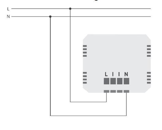
Installation
As a smart light
Connected to a switch
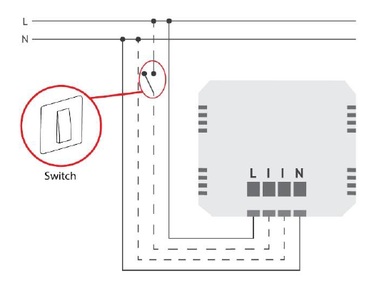
NOTE: Antenna positioning
Inclusion/Exclusion
On factory default the device does not belong to any Z-Wave network. The device needs to be added to an existing wireless network to communicate with the devices of this network. This process is called Inclusion.
Devices can also be removed from a network. This process is called Exclusion. Both processes are initiated by the primary controller of the Z-Wave network. This controller is turned into exclusion respective inclusion mode. Inclusion and Exclusion is then performed doing a special manual action right on the device.
Inclusion
1. Press once on button 2 - right.2. One press on button 3 - down for enabling full white.
3. When full white is enabled, press, and hold button 2 - right, between 4 and 6 seconds. After 6 seconds, the device starts flashing green (1 second ON, 0.5 second OFF). Once the device receives node ID (after 10 seconds), it stops flashing and turns full green. The procedure is always available.
Exclusion
2. One press on button 3 - down for enabling full white.
3. When full white is enabled, press, and hold button 2 - right for 5 seconds. After 5 seconds, the device starts flashing red 1 second ON, 0.5 second OFF. Once the device loses node ID (after 10 seconds), it stops flashing and turns full red. The procedure is always available.
Product Usage
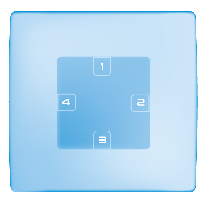
1. Turns ON/OFF the Luxy light Dims the Luxy light
2. Switches between 4 different lighting effects (ocean, sunrise, rainbow, and nature)
3. Turns ON/OFF the white light on the Luxy Dims the Luxy light
4. Starts the colour spectrum and stops at the colour you wish to have
Quick trouble shooting
Here are a few hints for network installation if things dont work as expected.
- Make sure a device is in factory reset state before including. In doubt exclude before include.
- If inclusion still fails, check if both devices use the same frequency.
- Remove all dead devices from associations. Otherwise you will see severe delays.
- Never use sleeping battery devices without a central controller.
- Dont poll FLIRS devices.
- Make sure to have enough mains powered device to benefit from the meshing
Association - one device controls an other device
Z-Wave devices control other Z-Wave devices. The relationship between one device controlling another device is called association. In order to control a different device, the controlling device needs to maintain a list of devices that will receive controlling commands. These lists are called association groups and they are always related to certain events (e.g. button pressed, sensor triggers, ...). In case the event happens all devices stored in the respective association group will receive the same wireless command wireless command, typically a 'Basic Set' Command.
Association Groups:
| Group Number | Maximum Nodes | Description |
|---|---|---|
| 1 | 1 | Lifeline |
| 2 | 5 | ON/OFF (Basic Set |
| 3 | 5 | Dim (Multilevel) |
| 4 | 5 | Change of color (Switch Color) |
Configuration Parameters
Z-Wave products are supposed to work out of the box after inclusion, however certain configuration can adapt the function better to user needs or unlock further enhanced features.
IMPORTANT: Controllers may only allow configuring signed values. In order to set values in the range 128 ... 255 the value sent in the application shall be the desired value minus 256. For example: To set a parameter to 200 it may be needed to set a value of 200 minus 256 = minus 56. In case of a two byte value the same logic applies: Values greater than 32768 may needed to be given as negative values too.
Parameter 1: Digital input type
Defines the input type of device connected to digital input. Size: 1 Byte, Default Value: 1
| Setting | Description |
|---|---|
| 0 | Push-button |
| 1 | ON/OFF toggle switch |
| 2 | Motion sensor |
| 3 | Motion sensor with memory (turned off after certain amount of time defined in parameter 5) |
Parameter 3: Turning off alarming
Size: 1 Byte, Default Value: 1
| Setting | Description |
|---|---|
| 0 | only by z-wave command (basic set, switch multilevel set, switch multilevel start/stop level change, sound switch play tone, sound switch configuration, switch color set, switch color start/stop level change, notification report idle) |
| 1 | capacitive input or z-wave command (basic set, switch multilevel set, switch multilevel start/stop level change, sound switch play tone, sound switch configuration, switch color set, switch color start/stop level change, notification report idle) |
Parameter 5: Motion sensor memory timer
Defines the time after which the output triggered by motion sensor is turned off. Size: 2 Byte, Default Value: 10
| Setting | Description |
|---|---|
| 0 - 32534 | 0-32534 seconds after which the LED will be turned off. |
| 32535 | never turns off |
Parameter 10: Auto on timer
Defines the time after which the device is turned to last known state. Size: 2 Byte, Default Value: 0
| Setting | Description |
|---|---|
| 0 | disabled |
| 30 - 32353 | seconds after which the device turns on |
Parameter 11: Auto off timer
Defines the time after which the device is turned to last known state. Size: 2 Byte, Default Value: 30
| Setting | Description |
|---|---|
| 0 | disabled |
| 30 - 32535 | seconds after which the device turns off |
Parameter 30: Restore state on power failure
Size: 1 Byte, Default Value: 1
| Setting | Description |
|---|---|
| 0 | disabled (the device will not restore state on power failure and will remain off) |
| 1 | enabled (the device will restore state on power failure) |
Parameter 50: Beeper enable/disable
This parameter affects beeper function just in case when the device receives the NOTIFICATION_REPORT. If the user sends a SOUND_SWITCH_TONE_PLAY_SET (1), the buzzer still emits a serviceable tone. Size: 1 Byte, Default Value: 1
| Setting | Description |
|---|---|
| 0 | disabled (the beeper is not active) |
| 1 | enabled (the beeper is active) |
Technical Data
| Dimensions | 93 x90 x 48 mm |
| Weight | 141 gr |
| Hardware Platform | ZM5101 |
| EAN | 3830062071796 |
| IP Class | IP 20 |
| Voltage | 230V |
| Device Type | Color Switch |
| Network Operation | Always On Slave |
| Z-Wave Version | 6.82.00 |
| Certification ID | ZC10-20096982 |
| Z-Wave Product Id | 0x0159.0x0008.0x0051 |
| Frequency | Europe - 868,4 Mhz |
| Maximum transmission power | 5 mW |
Supported Command Classes
- Association Grp Info V3
- Association V2
- Basic V2
- Configuration
- Device Reset Locally
- Manufacturer Specific V2
- Notification V8
- Powerlevel
- Security
- Security 2
- Sound Switch
- Supervision
- Switch Color V3
- Switch Multilevel V4
- Transport Service V2
- Version V2
- Zwaveplus Info V2
Controlled Command Classes
- Basic V2
- Switch Color V3
- Switch Multilevel V4
Explanation of Z-Wave specific terms
- Controller — is a Z-Wave device with capabilities to manage the network. Controllers are typically Gateways,Remote Controls or battery operated wall controllers.
- Slave — is a Z-Wave device without capabilities to manage the network. Slaves can be sensors, actuators and even remote controls.
- Primary Controller — is the central organizer of the network. It must be a controller. There can be only one primary controller in a Z-Wave network.
- Inclusion — is the process of adding new Z-Wave devices into a network.
- Exclusion — is the process of removing Z-Wave devices from the network.
- Association — is a control relationship between a controlling device and a controlled device.
- Wakeup Notification — is a special wireless message issued by a Z-Wave device to announces that is able to communicate.
- Node Information Frame — is a special wireless message issued by a Z-Wave device to announce its capabilities and functions.