Qubino
Smart Meter
SKU: GOAEZMNHTD1


Quickstart
This is a
- press service button S for more than 2 second
Important safety information
Please read this manual carefully. Failure to follow the recommendations in this manual may be dangerous or may violate the law. The manufacturer, importer, distributor and seller shall not be liable for any loss or damage resulting from failure to comply with the instructions in this manual or any other material. Use this equipment only for its intended purpose. Follow the disposal instructions. Do not dispose of electronic equipment or batteries in a fire or near open heat sources.Product Description
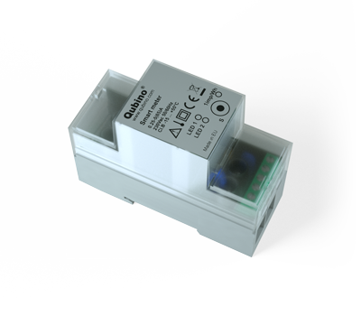
This Z-Wave module is used for energy measurements in single-phase electrical power network and can be used in residential, industrial and utility applications. Meters measure energy directly in 2-wire networks according to the principle of fast sampling of voltage and current signals. A built-in microprocessor calculates energy, power and power factor from the measured signals. The module can be controlled through Z-wave network and it acts as repeater in order to improve range and stability of Z-wave network. It is designed to be mounted on DIN rail.
Installation
- To prevent electrical shock and/or equipment damage, disconnect electrical power: remove main fuse or put on OFF position a main disconnection switch (or circuit breaker if it is compliant to standard IEC947-2), before installation or any servicing.
- Make sure, that no voltage is present in the installation.
- Prevent the disconnecting device from being switched on accidentally.
- Connect the module according to electrical diagram.
- Locate the antenna far from metal elements (as far as possible).
- Do not shorten the antenna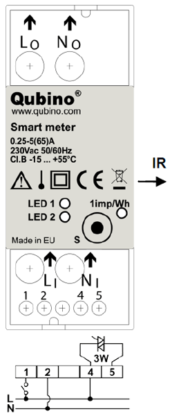
Notes for the diagram:
LI Live input
NI Neutral input
Lo Live output
No Neutral output
1 Input for IR external relay/Ext. relay
2 Neutral lead for input
4 Live lead for External relay output
5 Output for External relay (max. 3W)
S Service button (used to add or remove module from the Z-Wave network).
LED1 Green - Power on (solid) / no ID (blinking slow 1s) / Inc./Exc. mode (blinking fast 0,5s)
LED2 Yellow on – output on (any) / Yellow off – outputs off (both)
IR Output for IR external relay
1imp/Wh Red - Pulse rate (On – no load indication)
External relays
It is possible to connect two external relay to Smart Meter module. One controlled by built-in optical (IR) communication port on the side, second controlled by output on terminal 5. 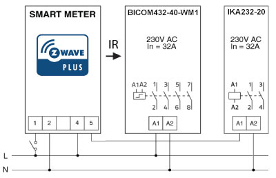
Product Usage
| Reset to factory default | - press service button S for more than 6 second |
| Inclusion | - press service button S for more than 2 second |
| Exclusion | - press service button S for more than 2 second (not all Parameters are reset) |
| NIF | XXXNIF |
| Wakeup | XXXWakeupDescription |
| Protection | XXXProtection |
| FirmwareUpdate | XXXFirmwareUpdate |
| SetAssociation | XXXSetAssociation |
Association Groups:
| Group Number | Maximum Nodes | Description |
|---|---|---|
| 1 | 1 | Lifeline |
Configuration Parameters
Parameter 7: Input 1 switch function selection
Size: 1 Byte, Default Value: 4
| Setting | Description |
|---|---|
| 0 | disabled |
| 2 | IR external relay control – mono stable push button |
| 3 | IR external relay control - bi stable switch |
| 4 | External relay control – mono stable push button |
| 5 | External relay control – bi stable switch |
Parameter 10: Activate / deactivate functions ALL ON / ALL OFF
Only for older Version! Size: 2 Byte, Default Value: 255
| Setting | Description |
|---|---|
| 255 | ALL ON active, ALL OFF active. |
| 0 | ALL ON is not active, ALL OFF is not active |
| 1 | ALL ON is not active, ALL OFF active |
| 2 | ALL ON active, ALL OFF is not active DIN Dimmer module responds to commands ALL ON / ALL OFF that may be sent by the main controller or by other controller belonging to the system. |
Parameter 11: Automatic turning off IR external relay output after set time
When IR external relay is ON it goes automatically OFF after time defined by this Parameter. Timer is reset to zero each time the module receive ON command regardless from where it comes (push button, associated module, controller,..) Size: 2 Byte, Default Value: 0
| Setting | Description |
|---|---|
| 0 - 59 | Auto OFF disabled |
| 60 - 32535 | Auto OFF enabled with define time, step is 1s |
Parameter 12: Automatic turning on IR external relay output after set time
When IR external relay is OFF it goes automatically ON after time defined by this Parameter. Timer is reset to zero each time the module receive OFF command regardless from where it comes (push button, associated module, controller,..). Size: 2 Byte, Default Value: 0
| Setting | Description |
|---|---|
| 0 - 59 | Auto ON disabled |
| 60 - 32535 | Auto ON enabled with define time, step is 1s. |
Parameter 13: Automatic turning off External relay output after set time
When External relay is ON it goes automatically OFF after time defined by this parameter. Timer is reset to zero each time the module receive ON command regardless from where it comes (push button, associated module, controller,..). Size: 2 Byte, Default Value: 0
| Setting | Description |
|---|---|
| 0 - 59 | Auto OFF disabled |
| 60 - 32535 | Auto OFF enabled with define time, step is 1s |
Parameter 14: Automatic turning on External relay after output set time
When External relay is OFF it goes automatically ON after time defined by this parameter. Timer is reset to zero each time the module receive OFF command regardless from where it comes (push button, associated module, controller,..). Size: 2 Byte, Default Value: 0
| Setting | Description |
|---|---|
| 0 - 59 | Auto ON disabled |
| 60 - 32535 | Auto ON enabled with define time, step is 1s |
Parameter 40: Power reporting in Watts on power change
Set value means percentage, set value from 0 - 100=0% - 100%. NOTE: if power changed is less than 1W, the report is not send (pushed), independent of percentage set. Size: 1 Byte, Default Value: 5
| Setting | Description |
|---|---|
| 0 | reporting disabled |
| 1 - 100 | 1% - 100% Reporting enabled. Power report is send (push) only when actual power in Watts in real time changes for more than set percentage comparing to previous actual power in Watts, step is 1%. |
Parameter 42: Power reporting in Watts by time interval
Set value means time interval (0 – 32767) in seconds, when power report is send. Size: 2 Byte, Default Value: 0
| Setting | Description |
|---|---|
| 0 - 59 | reporting disabled |
| 60 - 32767 | Reporting enabled. Power report is send with time interval set by entered value. Please note, that too fast reporting can cause too much Z-Wave traffic resulting in Z-Wave poor response |
Parameter 45: Reset Power counters
Size: 1 Byte, Default Value: 0
| Setting | Description |
|---|---|
| 0 | no function |
| 1 | reset counter 1 – KWh |
| 2 | reset counter 2 – kVARh |
| 4 | reset counter 3 – kVAh |
| 15 | reset ALL counters |
Parameter 100: Enable / Disable endpoints IR external relay and External relay
Enabling IR external relay and External relay or both of them, means that endpoint (IR external relay) and endpoint (External relay) or both will be present on UI. Disabling them will result in hiding endpoints according to Parameter set value. Note that hiding endpoint has no impact on its functionality.NOTE1: After parameter change, first exclude module (without setting parameters to default value) and then re include the module. NOTE2: If you dont have IR BiComm relay module mounted and you enable IR communication (parameter 100 is 2 or 3) there will be no valid IR relay state reported. It will be reported IR COMMUNICATION ERROR and LED2 will BLINK. Size: 1 Byte, Default Value: 0
| Setting | Description |
|---|---|
| 0 | Endpoints IR external relay and External relay disabled |
| 1 | Endpoints IR external relay disabled, External relay enabled |
| 2 | Endpoints IR external relay enabled, External relay disabled |
| 3 | Endpoints IR external relay and External relay enabled |
Parameter 110: Maximum Power auto off
Set value means Maximum Power Consumption (0 - 15000) in watts (W), when relays are turned off according to parameters no. 111 and 112. Size: 2 Byte, Default Value: 0
| Setting | Description |
|---|---|
| 0 | no function |
| 1 - 15000 | 1 W - 15000 W Maximum Power Consumption. |
Parameter 111: - Delay overpower off
Set value means number of second to power off relay (defined by parameters no. 110 and 112) before restart (30 - 32535) in seconds (s) Size: 2 Byte, Default Value: 30
| Setting | Description |
|---|---|
| 30 - 32535 | 30 s – 32535 s delay |
Parameter 112: Relay to power off
Set value selects relay to be powered off when threshold is reached (defined by parameters no. 110 and 111). Size: 1 Byte, Default Value: 0
| Setting | Description |
|---|---|
| 0 | switch between the 2 relays (power off relay 1 first, after power on, if power consumption is still over, power off relay 2, ..) |
| 1 | always power off relay 1 (IR external relay) |
| 2 | always power off relay 2 (External relay) |
| 3 | always power off both relays (relay 1 and relay 2) |
Parameter 130: Serial Number (Read Only)
Since Version 7.6 Size: 4 Byte, Default Value:
| Setting | Description |
|---|
Technical Data
| Dimensions | 36x90x64mm mm |
| Weight | 140 gr |
| Hardware Platform | ZM5202 |
| EAN | 3830062070362 |
| IP Class | IP 20 |
| Voltage | 230 V |
| Load | 65 A |
| Device Type | Smart Meter |
| Firmware Version | 07.06 |
| Z-Wave Version | 04.3d |
| Certification ID | ZC10-18086203 |
| Z-Wave Product Id | 0x0159.0x0007.0x0052 |
| Frequency | Europe - 868,4 Mhz |
| Maximum transmission power | 5 mW |