Qubinio
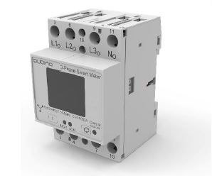
Qubino 3 phases Smart Meter
SKU: GOAEZMNHXD1


Quickstart
This is a
Toggle the Service button S between 0.2 and 6 seconds
Important safety information
Please read this manual carefully. Failure to follow the recommendations in this manual may be dangerous or may violate the law. The manufacturer, importer, distributor and seller shall not be liable for any loss or damage resulting from failure to comply with the instructions in this manual or any other material. Use this equipment only for its intended purpose. Follow the disposal instructions. Do not dispose of electronic equipment or batteries in a fire or near open heat sources.Product Description
The Qubino Smart Meter is an extremely versatile and powerful Z-Wave module for measuring energy in a single-phase electrical power network of up to 65A. A built-in microprocessor calculates energy, power and power factor from the measured signals. It is designed to be mounted on a DIN rail.
The Qubino Smart Meter can be used in residential, industrial and utility applications. It measures energy directly in 2-wire networks by means of fast sampling of voltage and current signals. It calculates energy, power and power factor from the measured signals. You can control the module through the Z-Wave network. It also acts as a repeater in order to improve the range and stability of the Z-Wave network. The Smart Meter is designed to be mounted on a DIN rail.
Properties:
- Z-Wave Plus
- EU frequency: 868.42 MHz
- Package content: 1x Qubino Smart Meter
Main terminals (LI,NI,Lo,No)
- Contacts capacity: 1.5...16(25)mm2
- Connection screws: M5
- Max torque: 3.5 Nm
Optional terminals (1,2,4,5)
- Contact capacity: 0.05 … 1 (2.5) mm2
- Connection screws: M3
- Max torque: 0.6 Nm
Measuring input
- Type (connection): single phase (1b)
- Reference current (Iref): 5 A
- Maximum current (Imax): 65 A
- Minimum current (Imin): 0.25 A
- Starting current: 20 mA
- Voltage (Un): 230 V (±20%)
- Power consumption at Un: < 2 W
- Nominal frequency (fn): 50 and 60 Hz
Accessory
- IKA232-20/230 V (GOAEIKA23220)
- BICOM432-40-WM1 (GOAEBICOM432)
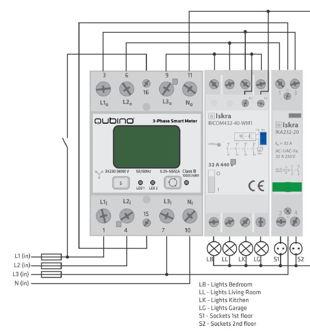
Installation
Step 2 – Installing the device:
- Connect the device exactly according to the diagrams shown below
 Step 3 – Turn ON the fuse:
Step 5 – The Installation is now complete. It’s time to make your life more comfortable with the help of the Qubino 3-Phase Smart Meter
Product Usage
The 3-Phase Smart Meter can be used in many different scenes, which can help make your life more comfortable. We have prepared a few of them for you so you can get an idea for your next smart home project. Of course, there are countless of other options for how to use Qubino 3-Phase Smart Meter to remotely control devices via your smartphone.

| Reset to factory default | Press and hold the S service button between 6 seconds and 20 seconds |
| Inclusion | Toggle the Service button S between 0.2 and 6 seconds |
| Exclusion | Toggle the Service button S between 0.2 and 6 seconds |
| NIF | XXXNIF |
| Wakeup | XXXWakeupDescription |
| Protection | XXXProtection |
| FirmwareUpdate | XXXFirmwareUpdate |
| SetAssociation | XXXSetAssociation |
Association Groups:
| Group Number | Maximum Nodes | Description |
|---|---|---|
| 1 | 1 | Lifeline |
Configuration Parameters
Parameter 7: Input switch function selection
Available configuration parameters for input switch I1 Size: 1 Byte, Default Value: 0
| Setting | Description |
|---|---|
| 0 | disabled |
| 2 | IR external relay control – mono stable push button |
| 3 | IR external relay control – bi-stable switch |
| 4 | External relay control – mono stable push button |
| 5 | External relay control – bi-stable switch |
Parameter 40: Reporting on power change
This parameter is valid for Active Power Total, Active Power Phase1, Active Power Phase2 and Active Power Phase3.
NOTE: if power change is less than 5 W, the report is not send (pushed).NOTE: Device is measuring also some disturbances even if on the output is no load. To avoid disturbances:- If measured Active Power (W) is below e.g. 5W-> the reported value in this case is 0W
Size: 1 Byte, Default Value: 50
| Setting | Description |
|---|---|
| 0 | reporting disabled |
| 1 - 100 | 1% - 100% reporting enabled. Power report is send only when actual power in Watts (in real time changes for more than set percentage comparing to previous Active Power, step is 1%. |
Parameter 42: Reporting on time interval
This parameter is currently valid only for Active Energy Total Import/Export (kWh), Reactive Energy Total (kvarh), Total Energy (kVAh)
Note: Device is reporting only if there was a change of 0.1 in EnergyNote: In the future will be possible to measure and report also Active Energy on PH1, PH2 and PH3.
Size: 2 Byte, Default Value: 600
| Setting | Description |
|---|---|
| 0 | reporting disabled |
| 600 - 65536 | Reporting enabled. Report is send with the time interval set by entered value. Seconds |
Parameter 43: Other Values - Reporting on time interval
This parameter is valid only for Voltage (V of ph1, ph2, ph3), Current (A of ph1, ph2, ph3), Total Power Factor, Total Reactive Power (var)
Note: Device is reporting only if there was a change
Size: 2 Byte, Default Value: 600
| Setting | Description |
|---|---|
| 0 | reporting disabled |
| 600 - 65536 | Reporting enabled. Report is send with the time interval set by entered value. Seconds |
Parameter 100: Enable / Disable External IR relay (BICOM)
NOTE1: After parameter change, first exclude module (without setting parameters to default value) and then re include the module.NOTE 2: If you don‘t have IR BICOM relay module mounted and you enable IR communication (parameter 100 is 1 or 2) there will be no valid IR relay state reported. It will be reported IR COMMUNICATION ERROR and LED2 will BLINK. Size: 1 Byte, Default Value: 0
| Setting | Description |
|---|---|
| 0 | External IR relay disabled |
| 1 | External IR relay enabled and connected to all 3 Phases |
| 2 | External IR relay enabled and connected to a Phase 1 |
Parameter 101: Enable / Disable External relay (IKA)
After parameter change, first exclude module (without setting parameters to default value) and then re include the module. Size: 1 Byte, Default Value: 0
| Setting | Description |
|---|---|
| 0 | External relay disabled |
| 1 | External relay enabled and connected to Phase 2 |
Parameter 106: External IR relay (BICOM) power threshold settings – maximum power of all phases together
This parameter defines a threshold when External IR relay is being turned off. (If Parameter no. 100 is set to the value 1 or 2)
NOTE: Meter is capable of measuring max 3x65A!
Size: 2 Byte, Default Value: 0
| Setting | Description |
|---|---|
| 0 | no function |
| 10 - 60000 | Watt |
Parameter 107: External relay (IKA) power threshold settings – maximum power on phase L2
This parameter defines a threshold when External relay is being turned off (if the parameter no. 100 is set to the value 1 or 2).
NOTE: Meter is capable of measuring max 65A
Size: 2 Byte, Default Value: 0
| Setting | Description |
|---|---|
| 0 | no function |
| 10 - 20000 | Watt |
Parameter 112: Power threshold – Delay before power on
External IR relay/ External relay is turned off due to detected overload (as set by parameter 106&107) and remains off for a time, defined in this parameter. After that time, the output turns on to check, if the overload is still present.
NOTE: the delay time may be prolonged for more then 10s of the time set by the parameter.
Size: 2 Byte, Default Value: 0
| Setting | Description |
|---|---|
| 0 | External IR relay/ External relay will not turn back on |
| 30 - 32535 | Seconds |
Technical Data
| Dimensions | 53,6 x 84 x 65 mm |
| Weight | 221 gr |
| Hardware Platform | ZM5101 |
| EAN | 3830062070683 |
| IP Class | IP 20 |
| Voltage | 3x 230 V/400V |
| Load | 65 A |
| Device Type | Smart Meter |
| Firmware Version | 01.00 |
| Z-Wave Version | 04.3d |
| Certification ID | ZC10-19066549 |
| Z-Wave Product Id | 0x0159.0x0007.0x0054 |
| Frequency | Europe - 868,4 Mhz |
| Maximum transmission power | 5 mW |