Qubino
Wetter Station
SKU: GOAEZMNHZD1


Quickstart
This is a
Important safety information
Please read this manual carefully. Failure to follow the recommendations in this manual may be dangerous or may violate the law. The manufacturer, importer, distributor and seller shall not be liable for any loss or damage resulting from failure to comply with the instructions in this manual or any other material. Use this equipment only for its intended purpose. Follow the disposal instructions. Do not dispose of electronic equipment or batteries in a fire or near open heat sources.What is Z-Wave?
Z-Wave is the international wireless protocol for communication in the Smart Home. This device is suited for use in the region mentioned in the Quickstart section.
Z-Wave ensures a reliable communication by reconfirming every message (two-way communication) and every mains powered node can act as a repeater for other nodes (meshed network) in case the receiver is not in direct wireless range of the transmitter.
This device and every other certified Z-Wave device can be used together with any other certified Z-Wave device regardless of brand and origin as long as both are suited for the same frequency range.
If a device supports secure communication it will communicate with other devices secure as long as this device provides the same or a higher level of security. Otherwise it will automatically turn into a lower level of security to maintain backward compatibility.
For more information about Z-Wave technology, devices, white papers etc. please refer to www.z-wave.info.
Product Description
Weather Station is used for measuring temperature, humidity, wind & rain properties and sending the measurement values to your Z-Wave network. The Weather Station can measure 10 different values: two sets of temperature/humidity sensors, wing gauge with 5 sensors (direction, velocity, wind gust, temperature and wind chill) and a rain sensor. With the use of the included Weather Station USB KEY all 10 values (end points) are sent and rendered in your home Z-Wave network. Qubino Weather Station Key is used for receiving Wireless data packages (from Thermo/ Hygro Sensor Ch1, Thermo/ Hygro Sensor Ch2, Rain Gauge, Wind Gauge) and sends it to the Z-Wave Controller.
The Key is designed to be plugged into the USB Power Adapter. Module receives data for Temperature, Wind Chill, Velocity, Wind Gust, Wind Direction, Humidity, Rain Rate and Battery Level for each Sensor. It is designed to act as repeater in order to improve range and stability of Z-wave network.
Prepare for Installation / Reset
Please read the user manual before installing the product.
In order to include (add) a Z-Wave device to a network it must be in factory default state. Please make sure to reset the device into factory default. You can do this by performing an Exclusion operation as described below in the manual. Every Z-Wave controller is able to perform this operation however it is recommended to use the primary controller of the previous network to make sure the very device is excluded properly from this network.
Reset to factory default
This device also allows to be reset without any involvement of a Z-Wave controller. This procedure should only be used when the primary controller is inoperable.
- hold service button S between 4 seconds and 8 seconds
By this function, all parameters of the module are set to default values, own ID is deleted and the module will include as unsecure next time.
Installation
- Connect the Weather Station Key into the USB Power Supply.
- Locate the module far from metal elements.
- Locate the module in the range of Z-Wave Network and in the range of all 433 MHz sensors.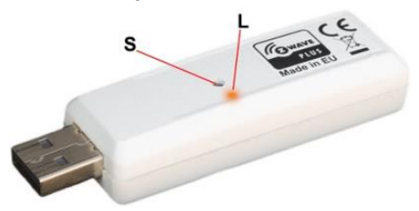
S Service button (used to add or remove module from the Z-Wave network).
L LED
Inclusion/Exclusion
On factory default the device does not belong to any Z-Wave network. The device needs to be added to an existing wireless network to communicate with the devices of this network. This process is called Inclusion.
Devices can also be removed from a network. This process is called Exclusion. Both processes are initiated by the primary controller of the Z-Wave network. This controller is turned into exclusion respective inclusion mode. Inclusion and Exclusion is then performed doing a special manual action right on the device.
Inclusion
- hold service button S between 1.5 and 4 secondsExclusion
- hold service button S between 1,5 seconds and 4 secondsIf service button S hold more than 1.5 and less than 4 seconds module is excluded, but configuration parameters are not set to default values and the module will include next time as it was set into the Configuration Parameter 250.
Product Usage
LED Blinking Meaning
- LED is 1 second ON and 1 second OFF The module is in exclusion mode
- LED is ON The module is in inclusion mode LED Blinks 1 time fast The module received data from Thermo/Hygro Sensor Ch1
- LED Blinks 2 time fast The module received data from Thermo/Hygro Sensor Ch2
- LED Blinks 3 time fast The module received data from Wind Sensor
- LED Blinks 4 time fast The module received data from Rain Sensor
Remote Weather Sensors
The remote weather sensors include a thermo-hygrometer, anemometer (wind sensor) and rain sensor. All data collected by the sensors are transmitted to the Weather Station Key by wireless RF, with a range up to 100 meters (open area). The Weather station Key supports a maximum of 2 thermo-hygrometers, allowing 2 channels of temperature/humidity display (Ch1 and Ch2). Setting up the Remote Weather Sensors Before starting up the Weather Station Key, setup all the remote sensors first. When placing the sensors, make sure that they are within receiving range of the console unit. Ideally, they should be within the line of sight of the console unit. Transmission range may be affected by trees, metal structures and electronic appliances. Test reception before permanently mounting your weather station. Also make sure that the sensors are easily accessible for cleaning and maintenance. The remote sensors should be cleaned on a weekly basis, since dirt and debris will affect sensor accuracy.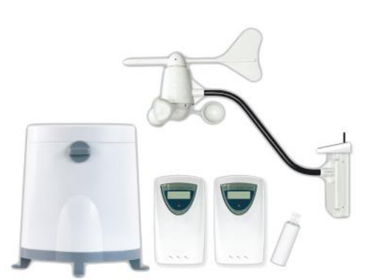
Setting up the Thermo-Hygro Sensor(s)
1. Open the latch at the base of the thermo-hygro sensor.
2. Set the channel with a slide switch to Ch1 or Ch2 (Channel has to be selected before inserting a battery’s)
3. Insert two 2 x UM-3 or “AA” size 1.5 V batteries.
4. Use a pin to press the “RESET” key which is in the battery compartment of thermo-hygro sensors after LED flash.
5. Replace the latch and mount the unit at desired location.
Placement Tips:
- The thermo-hygro sensor should be in an area with free air circulation and sheltered from direct sunlight and other extreme weather conditions. Place the unit in a shaded area, such as under a roof.
- Avoid placing the sensor near sources of heat such as chimneys.
- Avoid any areas which collect and radiate heat in the sun, such as metal, brick or concrete structures, paving, patios and decks.
- Ideally, place the sensor above natural surfaces such as a grassy lawn.
- The international standard height for measurements of air temperature is at 1.25m (4 ft) above ground level.
Setting up the Rain Sensor
1. Unlock the funnel-shaped top of the rain sensor by turning both knobs on the sides of the rain sensor in an anti-clockwise direction.
2. Lift the top off the base and insert two 2 x UM-3 or “AA” size 1.5 V batteries into the battery holder.
3. Replace the lid and secure into place by turning the knobs clockwise.
4. Place the rain sensor in a location such that precipitation can fall directly into the sensor, ideally 2-3 ft above the ground. It may be secured into place by using the four screws provided.
5. The sensor must be accurately levelled for optimum performance. To check if the sensor is levelled, remove the lid and check if the ball bearing inside is at the midpoint of the leveller. Additionally, a bubble level or carpenter’s level may be used.
6. Attach the protective screen onto the top of the lid. The screen will prevent any debris entering the sensor.
Placement Tips:
- The rain sensor should be placed in an open area away from walls, fences, trees and other coverings which may either reduce the amount of rainfall into the sensor, deflect the entry of wind
- blown rain, or create extra precipitation runoff. Trees and rooftops may also be sources of pollen and debris.
- To avoid rain shadow effects, place the sensor at a horizontal distance corresponding to two to four times the height of any nearby obstruction.
- It is important that rain excess can flow freely away from the sensor. Make sure that water does not collect at the base of the unit.
- The rainfall measurement mechanism utilizes a magnet; hence do not place any magnetic objects around the proximity of the sensor.
Setting up the Anemometer (Wind Sensor)
1. Assemble the wind cups and wind vane to the anemometer arm
2. Attach the assembled anemometer to the base.
3. Insert two 2 x UM-3 or “AA” size 1.5 V batteries into the battery holder in the base and connect the second battery to the solar panel connector.
4. Mount the anemometer onto a vertical surface, using the fittings provided.
Placement Tips:
- Check that wind can travel freely around the anemometer and is not distorted by nearby buildings, trees or other structures.
- For better results, place the anemometer at least 3 m above local structures and obstacles. The ground creates a frictional effect to wind flow and will attenuate readings.
- Aim for maximum exposure of the anemometer to the commonest wind directions in your area.
- The official mounting location for anemometers is 10m (33 ft) above ground level in a clear unobstructed location.
Maintenance
Changing Batteries
The battery statuses of the sensors are checked every hour. If the low battery indicators light up, replace the batteries for the corresponding unit immediately.
Changing Batteries for the Remote Sensors
1. Replace the batteries following the setup instructions for the corresponding sensor.
2. When the batteries are properly installed, the sensor will resume sending signals to the main console unit.
Cleaning
The Weather Station Key and outer casings for the remote sensors can be cleaned with a damp cloth. Small parts can be cleaned with a cotton tip or pipe-cleaner. Never use any abrasive cleaning agents and solvents. Do not immerse any units with electronic parts in water or under running water.
Anemometer
- Check that the wind vane and wind cups can spin freely and are free from dirt, debris or spider webs. Rain Sensor Like all rain gauges, the rain sensor is prone to blockages due to its funnel shape. Checking and cleaning the rain sensor from time to time will maintain the accuracy of rain measurements.
- Detach the protective screen and lid. Remove any dirt, leaves or debris by cleaning the items with soapy water and a damp cloth. Clean small holes and parts with a cotton tips or pipe-cleaner.
- Look out for spiders or insects that might have crawled into the funnel.
- Also clean the swinging mechanism with a damp cloth.
Quick trouble shooting
Here are a few hints for network installation if things dont work as expected.
- Make sure a device is in factory reset state before including. In doubt exclude before include.
- If inclusion still fails, check if both devices use the same frequency.
- Remove all dead devices from associations. Otherwise you will see severe delays.
- Never use sleeping battery devices without a central controller.
- Dont poll FLIRS devices.
- Make sure to have enough mains powered device to benefit from the meshing
Association - one device controls an other device
Z-Wave devices control other Z-Wave devices. The relationship between one device controlling another device is called association. In order to control a different device, the controlling device needs to maintain a list of devices that will receive controlling commands. These lists are called association groups and they are always related to certain events (e.g. button pressed, sensor triggers, ...). In case the event happens all devices stored in the respective association group will receive the same wireless command wireless command, typically a 'Basic Set' Command.
Association Groups:
| Group Number | Maximum Nodes | Description |
|---|---|---|
| 1 | 1 | Lifeline |
| 2 | 16 | basic on/off (triggered when the Wind Gust of the Wind Gauge exceed the Configuration Parameter 1 Value) |
| 3 | 16 | basic on/off (triggered when the Rain rate exceed the Configuration Parameter 2 Value) |
Configuration Parameters
Z-Wave products are supposed to work out of the box after inclusion, however certain configuration can adapt the function better to user needs or unlock further enhanced features.
IMPORTANT: Controllers may only allow configuring signed values. In order to set values in the range 128 ... 255 the value sent in the application shall be the desired value minus 256. For example: To set a parameter to 200 it may be needed to set a value of 200 minus 256 = minus 56. In case of a two byte value the same logic applies: Values greater than 32768 may needed to be given as negative values too.
Parameter 1: Wind Gauge, Wind Gust Top Value
If the Wind Gust is Higher than the Parameter Value, a device triggers an Association Size: 2 Byte, Default Value: 1000
| Setting | Description |
|---|---|
| 0 - 8800 | 0 – 8800 = value from 0.00 m/s to 88.00 m/s |
Parameter 2: Rain Gauge, Rain Rate Top Value
If the Sensor Rain Rate is Higher than the Parameter Value, a device triggers an Association Size: 2 Byte, Default Value: 200
| Setting | Description |
|---|---|
| 0 - 30000 | value from 0.00 mm/h to 300.00 mm/h |
Parameter 3: Wind Gauge, Wind Gust
Size: 1 Byte, Default Value: 1
| Setting | Description |
|---|---|
| 0 | If the Wind Gust is Higher than the Parameter No. 1 Value, then a Device sends Basic Set = 0x00. |
| 1 | If the Wind Gust is Higher than the Parameter No. 1 Value, then a Device sends Basic Set = 0xFF.) |
Parameter 4: Rain Gauge, Rain Rate
Size: 1 Byte, Default Value: 1
| Setting | Description |
|---|---|
| 0 | If the Rain amount is Higher than the Parameter No. 2 Value, then a Device sends Basic Set = 0x00. |
| 1 | If the Rain amount is Higher than the Parameter No. 2 Value, then a Device sends Basic Set = 0xFF.) |
Parameter 5: End point 1 – Unsolicited Report
Unsolicited Report - If you enable Unsolicited Reports on the End Points, the USB Key will send data to the controller every time it receives data from the 433MHz sensors, which are different from the precious data. Size: 1 Byte, Default Value: 1
| Setting | Description |
|---|---|
| 0 | Unsolicited Report disabled |
| 1 | Unsolicited Report enabled |
Parameter 6: End point 2 – Unsolicited Report
Unsolicited Report - If you enable Unsolicited Reports on the End Points, the USB Key will send data to the controller every time it receives data from the 433MHz sensors, which are different from the precious data. Size: 1 Byte, Default Value: 1
| Setting | Description |
|---|---|
| 0 | Unsolicited Report disabled |
| 1 | Unsolicited Report enabled |
Parameter 7: End point 3 – Unsolicited Report
Unsolicited Report - If you enable Unsolicited Reports on the End Points, the USB Key will send data to the controller every time it receives data from the 433MHz sensors, which are different from the precious data. Size: 1 Byte, Default Value: 1
| Setting | Description |
|---|---|
| 0 | Unsolicited Report disabled |
| 1 | Unsolicited Report enabled |
Parameter 8: End point 4 – Unsolicited Report
Unsolicited Report - If you enable Unsolicited Reports on the End Points, the USB Key will send data to the controller every time it receives data from the 433MHz sensors, which are different from the precious data. Size: 1 Byte, Default Value: 1
| Setting | Description |
|---|---|
| 0 | Unsolicited Report disabled |
| 1 | Unsolicited Report enabled |
Parameter 9: End point 5 – Unsolicited Report
Unsolicited Report - If you enable Unsolicited Reports on the End Points, the USB Key will send data to the controller every time it receives data from the 433MHz sensors, which are different from the precious data. Size: 1 Byte, Default Value: 1
| Setting | Description |
|---|---|
| 0 | Unsolicited Report disabled |
| 1 | Unsolicited Report enabled |
Parameter 10: End point 6 – Unsolicited Report
Unsolicited Report - If you enable Unsolicited Reports on the End Points, the USB Key will send data to the controller every time it receives data from the 433MHz sensors, which are different from the precious data. Size: 1 Byte, Default Value: 1
| Setting | Description |
|---|---|
| 0 | Unsolicited Report disabled |
| 1 | Unsolicited Report enabled |
Parameter 11: End point 7 – Unsolicited Report
Unsolicited Report - If you enable Unsolicited Reports on the End Points, the USB Key will send data to the controller every time it receives data from the 433MHz sensors, which are different from the precious data. Size: 1 Byte, Default Value: 1
| Setting | Description |
|---|---|
| 0 | Unsolicited Report disabled |
| 1 | Unsolicited Report enabled |
Parameter 12: End point 8 – Unsolicited Report
Unsolicited Report - If you enable Unsolicited Reports on the End Points, the USB Key will send data to the controller every time it receives data from the 433MHz sensors, which are different from the precious data. Size: 1 Byte, Default Value: 1
| Setting | Description |
|---|---|
| 0 | Unsolicited Report disabled |
| 1 | Unsolicited Report enabled |
Parameter 13: End point 9 – Unsolicited Report
Unsolicited Report - If you enable Unsolicited Reports on the End Points, the USB Key will send data to the controller every time it receives data from the 433MHz sensors, which are different from the precious data. Size: 1 Byte, Default Value: 1
| Setting | Description |
|---|---|
| 0 | Unsolicited Report disabled |
| 1 | Unsolicited Report enabled |
Parameter 14: End point 10 – Unsolicited Report
Unsolicited Report - If you enable Unsolicited Reports on the End Points, the USB Key will send data to the controller every time it receives data from the 433MHz sensors, which are different from the precious data. Size: 1 Byte, Default Value: 1
| Setting | Description |
|---|---|
| 0 | Unsolicited Report disabled |
| 1 | Unsolicited Report enabled |
Parameter 15: Random ID Enable
If Random ID is disabled, the Weather Station USB Key can receive data from multiple 433 MHz Sensors on the same Channel. If the Random ID is enabled, the USB Key can receive data from only one sensor on the same channel. If the USB Key does not receive a data from a sensor on a specific channel for more than 2.5 hours, it clears the Random ID of the device and waits for a new ID. If you replace the batteries in the modules, the Random ID will change. If you want that the USB Key accept a module immediately, set the Parameter No. 15 to “0” and in the next step again to “1”. Size: 1 Byte, Default Value: 0
| Setting | Description |
|---|---|
| 0 | Random ID disabled |
| 1 | Random ID enabled |
Parameter 250: Unsecure / Secure Inclusion
The Weather Station Key supports both, the secure and unsecure inclusion. Even if the controller does not support security command classes, the Key could be included as unsecure and keep all the functionality. By default, the Key includes as unsecure. Size: 1 Byte, Default Value: 0
| Setting | Description |
|---|---|
| 0 | Unsecure Inclusion |
| 1 | Secure Inclusion |
Technical Data
| Dimensions | 460x120x430 mm |
| Weight | 1060 gr |
| Hardware Platform | ZM5202 |
| EAN | 3830062070560 |
| IP Class | IP 20 |
| Voltage | 230 V |
| Device Type | Weather Station USB Key |
| Generic Device Class | Multilevel Sensor |
| Specific Device Class | Routing Multilevel Sensor |
| Firmware Version | 01.02 |
| Z-Wave Version | 04.05 |
| Z-Wave Product Id | 0x0159.0x0007.0x0053 |
| Frequency | Europe - 868,4 Mhz |
| Maximum transmission power | 5 mW |
Supported Command Classes
- Basic
- Sensor Multilevel
- Association Grp Info
- Device Reset Locally
- Zwaveplus Info
- Multi Channel
- Configuration
- Manufacturer Specific
- Powerlevel
- Firmware Update Md
- Battery
- Association
- Multi Channel Association
- Version
Controlled Command Classes
- Basic
Explanation of Z-Wave specific terms
- Controller — is a Z-Wave device with capabilities to manage the network. Controllers are typically Gateways,Remote Controls or battery operated wall controllers.
- Slave — is a Z-Wave device without capabilities to manage the network. Slaves can be sensors, actuators and even remote controls.
- Primary Controller — is the central organizer of the network. It must be a controller. There can be only one primary controller in a Z-Wave network.
- Inclusion — is the process of adding new Z-Wave devices into a network.
- Exclusion — is the process of removing Z-Wave devices from the network.
- Association — is a control relationship between a controlling device and a controlled device.
- Wakeup Notification — is a special wireless message issued by a Z-Wave device to announces that is able to communicate.
- Node Information Frame — is a special wireless message issued by a Z-Wave device to announce its capabilities and functions.