Heatit (Thermo-Floor)
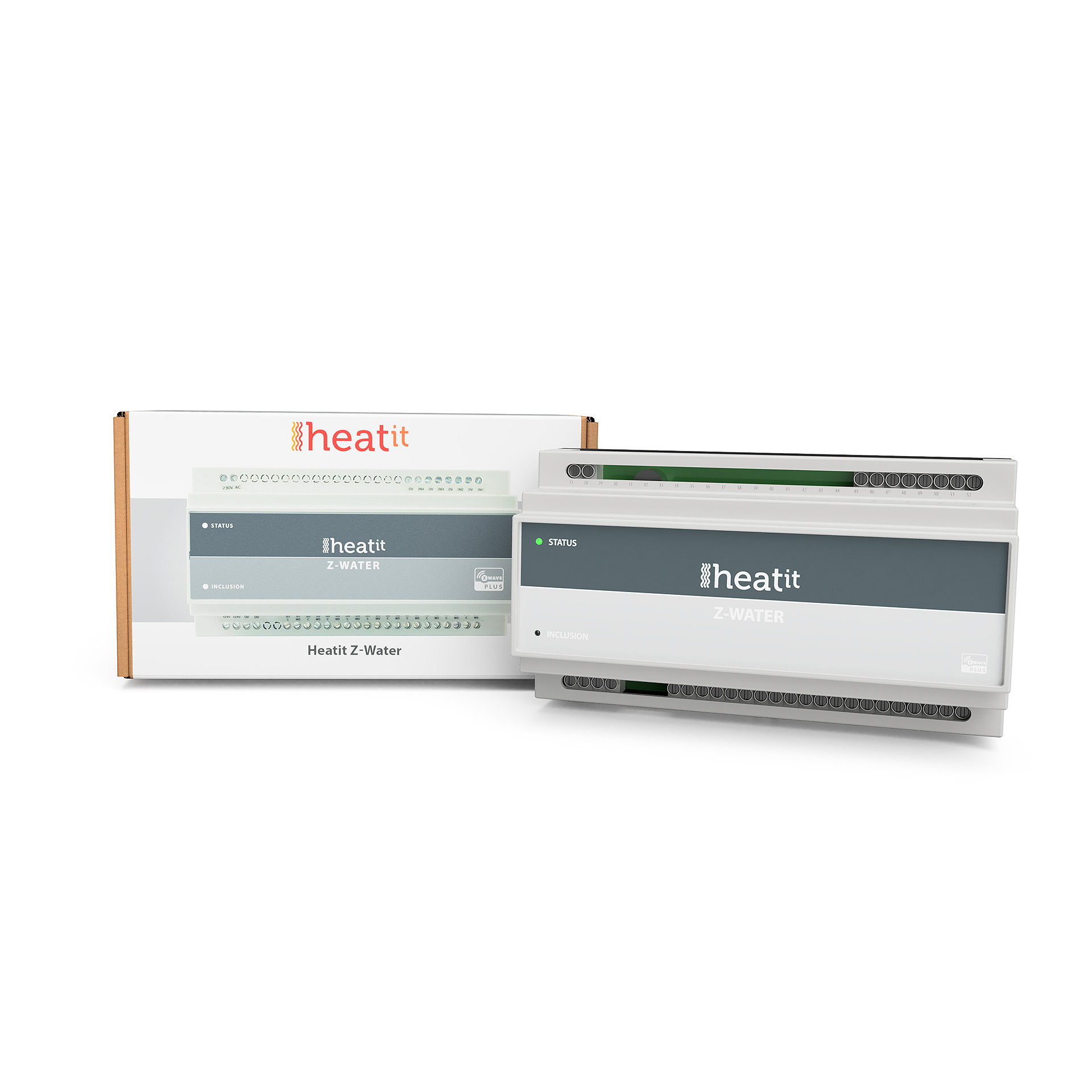
Heatit Z-Water
SKU: HEAE4512475


Quickstart
This is a
Important safety information
Please read this manual carefully. Failure to follow the recommendations in this manual may be dangerous or may violate the law. The manufacturer, importer, distributor and seller shall not be liable for any loss or damage resulting from failure to comply with the instructions in this manual or any other material. Use this equipment only for its intended purpose. Follow the disposal instructions. Do not dispose of electronic equipment or batteries in a fire or near open heat sources.Product Description
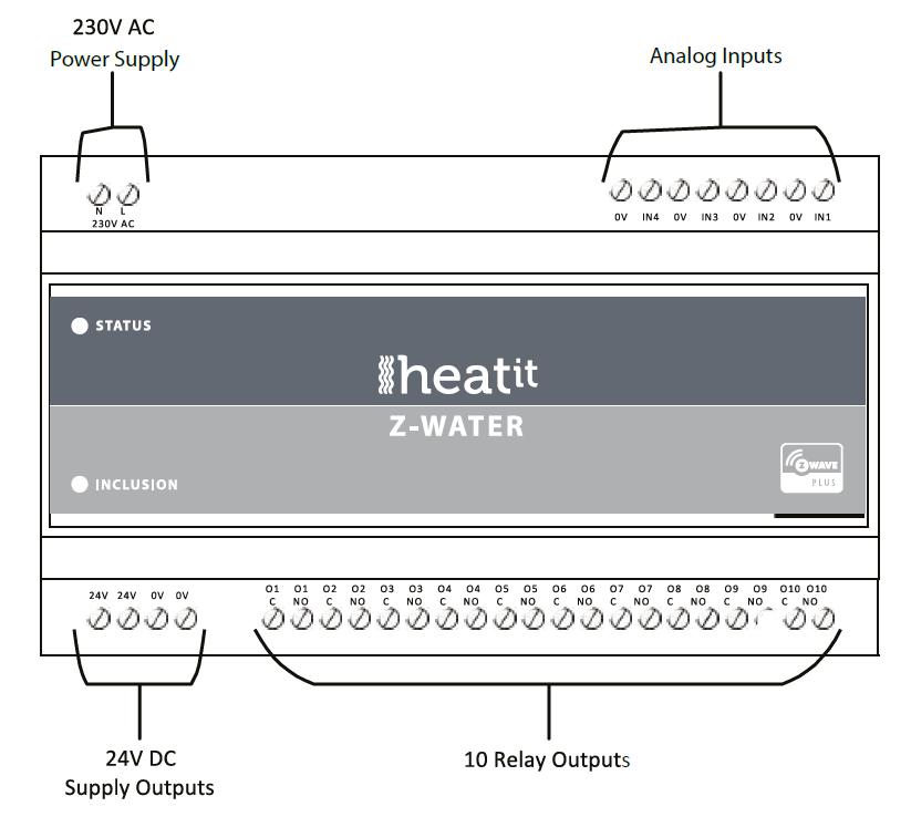
Heatit Z-Water is equipped with 10 relay outputs and 4 analog inputs, and a Z-Wave radio for interfacing to the wirelessZ-Wave network.The regulator can be power supplied from a 230V AC mains connection, and is able to deliver an output supply of 24V DC.Heatit Z-Water relay outputs are able to be freely controlled from the Z-Wave network, and can be used for severalpurposes, e.g. on/off control of light, control of valve actuators for an underfloor heating system, or control of other homeautomation systems.Heatit Z-Water inputs are analog inputs for interfacing simple temperature sensors; NTC, PT1000, etc.It is possible to configure the level and the indication of the status indicator LED in the front of the Heatit Z-Waterregulator.
Installation
Note: When mounting DIN Rail products, use a flathead screwdriver to pull the DIN Rail release tab while snapping the device on to the DIN Rail.
Preparing and connecting wires
Fuse: 3.15A Quick-Acting, UMF 250 Schurter Inc., part no.: 3405.0171.11
Analog Inputs
24V DC Supply Outputs
Terminals for the 24V DC power supply output that can be used to be switched through the relay outputs.
Inputs
24 V DC Output
24V DC output - Maximum 1.17A, 28W
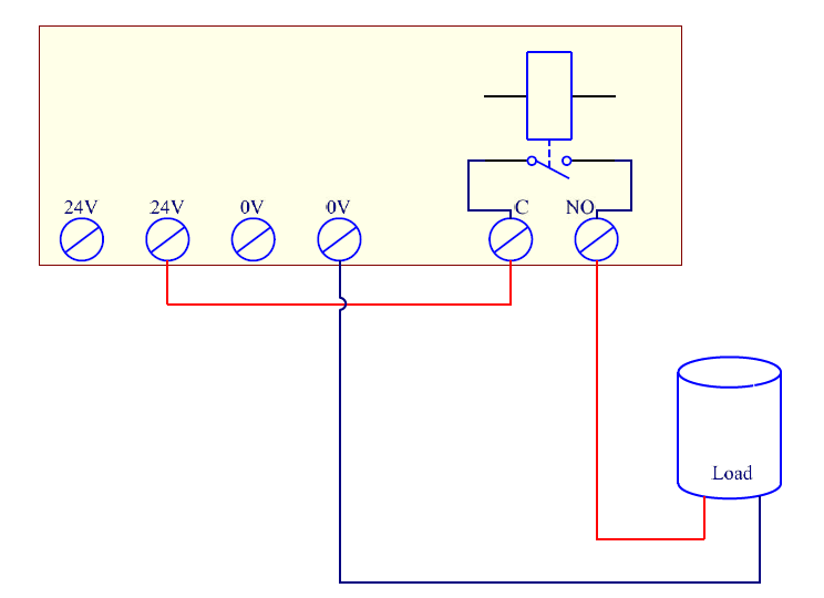
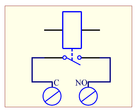
Schematic outline example of how the 24V supply output, together with a relay output, can be used to control a load.
| Reset to factory default | Press the small button through the little hole, marked with the text INCLUSION, in front of the Heatit Z-Water regulator for at least 10 seconds. |
| Inclusion | Press the INCLUSION button once on the device. |
| Exclusion | Press the INCLUSION button once on the device. |
| NIF | XXXNIF |
| Wakeup | XXXWakeupDescription |
| Protection | XXXProtection |
| FirmwareUpdate | XXXFirmwareUpdate |
| SetAssociation | XXXSetAssociation |
Association Groups:
| Group Number | Maximum Nodes | Description |
|---|---|---|
| 1 | 5 | Lifeline.- Reset notification- Basic Report On / Off- Multilevel Sensor Report |
| 2 | 5 | Sends Multilevel Sensor Reports for input 1. |
| 3 | 5 | Sends Multilevel Sensor Reports for input 2. |
| 4 | 5 | Sends Multilevel Sensor Reports for input 3. |
| 5 | 5 | Sends Multilevel Sensor Reports for input 4. |
Configuration Parameters
Parameter 1: Status LED
Configuration of the status LED. Size: 1 Byte, Default Value: 1
| Setting | Description |
|---|---|
| 0 | LED turned off |
| 1 | LED turned on. (Default) |
| 2 | LED flashing at 1 second intervals (0.5 Hz). |
| 3 | LED flashing at 0.5 second interval (1 Hz). |
Parameter 2: Status LED brightness level
Configure the percentage of light in the status LED, when the LED is turned on. Size: 1 Byte, Default Value: 50
| Setting | Description |
|---|---|
| 0 - 100 | Specifies the brightness level of the LED when it is on. Default is 50. |
Parameter 3: Thermistor type connected to input 1
This parameter decides which kind of thermistor that is connected to the input. Size: 1 Byte, Default Value: 1
| Setting | Description |
|---|---|
| 0 | No thermistor, input is disabled. |
| 1 | 10K NTC. (PART NUMBER: TT02-10KC3-93D-3000R-TPH). (Default) |
Parameter 4: Thermistor type connected to input 2
This parameter decides which kind of thermistor that is connected to the input. Size: 1 Byte, Default Value: 1
| Setting | Description |
|---|---|
| 0 | No thermistor, input is disabled. |
| 1 | 10K NTC. (PART NUMBER: TT02-10KC3-93D-3000R-TPH). (Default) |
Parameter 5: Thermistor type connected to input 3.
This parameter decides which kind of thermistor that is connected to the input. Size: 1 Byte, Default Value: 1
| Setting | Description |
|---|---|
| 0 | No thermistor, input is disabled. |
| 1 | 10K NTC. (PART NUMBER: TT02-10KC3-93D-3000R-TPH). (Default) |
Parameter 6: Thermistor type connected to input 4
This parameter decides which kind of thermistor that is connected to the input. Size: 1 Byte, Default Value: 1
| Setting | Description |
|---|---|
| 0 | 10K NTC. (PART NUMBER: TT02-10KC3-93D-3000R-TPH). (Default) |
| 1 | 10K NTC. (PART NUMBER: TT02-10KC3-93D-3000R-TPH). (Default) |
Parameter 7: Input 1 calibration
Configures the functionality of input 1. Size: 1 Byte, Default Value: 0
| Setting | Description |
|---|---|
| -40 - 40 | -4.0 degrees C4.0 degrees C. Default is 0 (0.0 degrees C). |
Parameter 8: Input 2 calibration
Configures the functionality of input 2. Size: 1 Byte, Default Value: 0
| Setting | Description |
|---|---|
| -40 - 40 | -4.0 degrees C4.0 degrees C. Default is 0 (0.0 degrees C). |
Parameter 9: Input 3 calibration
Configures the functionality of input 3. Size: 1 Byte, Default Value: 0
| Setting | Description |
|---|---|
| -40 - 40 | -4.0 degrees C4.0 degrees C. Default is 0 (0.0 degrees C). |
Parameter 10: Input 4 calibration.
Configures the functionality of input 4. Size: 1 Byte, Default Value: 0
| Setting | Description |
|---|---|
| -40 - 40 | -4.0 degrees C4.0 degrees C. Default is 0 (0.0 degrees C). |
Parameter 11: Input 1 report interval
Time interval between consecutive temperature reports. Temperature reports can be also sent as a result of polling. Size: 2 Byte, Default Value: 6
| Setting | Description |
|---|---|
| 0 | Reporting of temperatures disabled. |
| 1 - 8640 | Multiply with 10 seconds, 10 seconds24 hours. Default is 6 (60 seconds). |
Parameter 12: Input 2 report interval
Time interval between consecutive temperature reports. Temperature reports can be also sent as a result of polling. Size: 2 Byte, Default Value: 6
| Setting | Description |
|---|---|
| 0 | Reporting of temperatures disabled. |
| 1 - 8640 | Multiply with 10 seconds, 10 seconds24 hours. Default is 6 (60 seconds). |
Parameter 13: Input 3 report interval
Time interval between consecutive temperature reports. Temperature reports can be also sent as a result of polling. Size: 2 Byte, Default Value: 6
| Setting | Description |
|---|---|
| 0 | Reporting of temperatures disabled. |
| 1 - 8640 | Multiply with 10 seconds, 10 seconds24 hours. Default is 6 (60 seconds). |
Parameter 14: Input 4 report interval
Time interval between consecutive temperature reports. Temperature reports can be also sent as a result of polling. Size: 2 Byte, Default Value: 6
| Setting | Description |
|---|---|
| 0 | Reporting of temperatures disabled. |
| 1 - 8640 | Multiply with 10 seconds, 10 seconds24 hours. Default is 6 (60 seconds). |
Technical Data
| Dimensions | 16 x 58 x 86 mm |
| Weight | 320 gr |
| Hardware Platform | ZM5101 |
| EAN | 7071236014065 |
| IP Class | IP 20 |
| Voltage | 230V |
| Load | 5A |
| Device Type | Valve |
| Network Operation | Always On Slave |
| Z-Wave Version | 6.71.03 |
| Certification ID | ZC10-19036400 |
| Z-Wave Product Id | 0x019B.0x0003.0x020A |
| Firmware Updatable | Updatable by Consumer by RF |
| Loads Controlled | 10 |
| Supported Notification Types | |
| Electric Load Type | Dimmable ELV (Magnetic)Dimmable FluorescentDimmable LEDDimmable MLV (Magnetic)ELV (Electronic)FluorescentIncandescentInductive (e.g. Motor)LEDMLV (Magnetic) |
| Sensors | Air Temperature |
| Frequency | Europe - 868,4 Mhz |
| Maximum transmission power | 5 mW |