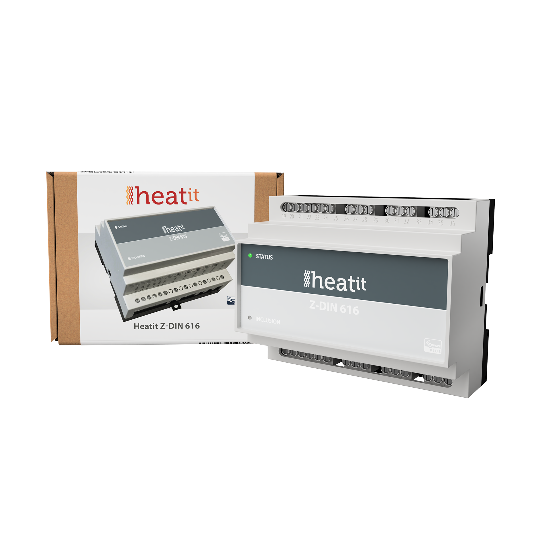
Heatit (Thermo-Floor)
Z-Din 616
SKU: HEAE4512561


Quickstart
This is a
Press the "INKLUSIION" button once.
Important safety information
Please read this manual carefully. Failure to follow the recommendations in this manual may be dangerous or may violate the law. The manufacturer, importer, distributor and seller shall not be liable for any loss or damage resulting from failure to comply with the instructions in this manual or any other material. Use this equipment only for its intended purpose. Follow the disposal instructions. Do not dispose of electronic equipment or batteries in a fire or near open heat sources.Product Description
Installation
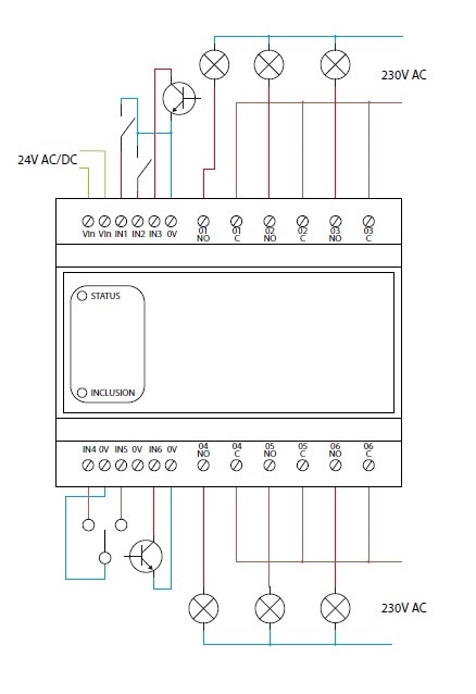
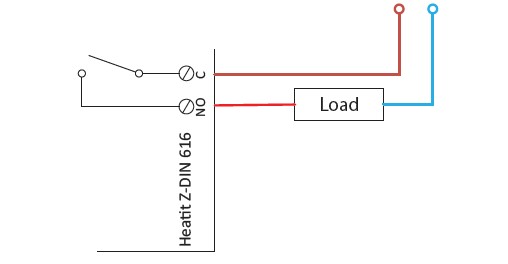
Relay Output
The 6 outputs of the Heatit Z-DIN 616 module consist of 1-pole SPST connectors (Single-Pole Single-Throw).
Inputs
| Reset to factory default | Resetting is performed by activating the small pushbutton marked INCLUSION located on the front for at least 10 seconds until the LED flashes briefly. E.g. slide a needle pin or a toothpick through the small hole to activate the pushbutton. |
| Inclusion | Press the "INKLUSIION" button once. |
| Exclusion | Press the "INKLUSIION" button once. |
| NIF | XXXNIF |
| Wakeup | XXXWakeupDescription |
| Protection | XXXProtection |
| FirmwareUpdate | XXXFirmwareUpdate |
| SetAssociation | XXXSetAssociation |
Association Groups:
| Group Number | Maximum Nodes | Description |
|---|---|---|
| 1 | 5 | Lifeline |
| 2 | 5 | IN1 Basic Set |
| 3 | 5 | IN1 Switch Binary |
| 4 | 5 | IN1 Multilevel |
| 5 | 5 | IN2 Basic Set |
| 6 | 5 | IN2 Switch Binary |
| 7 | 5 | IN2 Multilevel |
| 8 | 5 | IN3 Basic Set |
| 9 | 5 | IN3 Switch Binary |
| 10 | 5 | IN3 Multilevel |
| 11 | 5 | IN4 Basic Set |
| 3 | 12 | IN4 Switch Binary |
| 13 | 5 | IN4 Multilevel |
| 14 | 5 | IN5 Basic Set |
| 15 | 5 | IN5 Switch Binary |
| 16 | 5 | IN5 Multilevel |
| 17 | 5 | IN6 Basic Set |
| 18 | 5 | IN6 Switch Binary |
| 19 | 5 | IN6 Multilevel |
Configuration Parameters
Parameter 1: Status of LED
This parameter can be used to change the mode of the front-mounted status LED. Size: 1 Byte, Default Value: 1
| Setting | Description |
|---|---|
| 0 | The LED is Off. |
| 2 | The LED is steadily lit-up. |
| 2 | The LED flashes in 1 second interval (1 Hz). |
| 3 | The LED flashes in 1⁄2 second interval (1⁄2 Hz). |
Parameter 2: Brightness of status LED
nDetermines the brightness of the status LED. Size: 1 Byte, Default Value: 50
| Setting | Description |
|---|---|
| 0 | Switch off LED. |
| 1 - 99 | Brightness level (%) |
Parameter 3: Function setup of input 1
Select the value from the table below. Please refer to the section reg. input functions. Size: 1 Byte, Default Value: 3
| Setting | Description |
|---|---|
| 0 | Inactive. |
| 1 | Mode 1, level-controlled input. |
| 2 | Mode 2, falling-edge controlled input. |
| 3 | Mode 3, rising-edge controlled input. |
Parameter 4: Function setup of input 2
Select the value from the table below. Please refer to the section reg. input functions. Size: 1 Byte, Default Value: 3
| Setting | Description |
|---|---|
| 0 | Inactive. |
| 1 | Mode 1, level-controlled input. |
| 2 | Mode 2, falling-edge controlled input. |
| 3 | Mode 3, rising-edge controlled input. |
Parameter 5: Function setup of input 3
Select the value from the table below. Please refer to the section reg. input functions. Size: 1 Byte, Default Value: 3
| Setting | Description |
|---|---|
| 0 | Inactive. |
| 1 | Mode 1, level-controlled input. |
| 2 | Mode 2, falling-edge controlled input. |
| 3 | Mode 3, rising-edge controlled input. |
Parameter 6: Function setup of input 4
Select the value from the table below. Please refer to the section reg. input functions. Size: 1 Byte, Default Value: 3
| Setting | Description |
|---|---|
| 0 | Inactive. |
| 1 | Mode 1, level-controlled input. |
| 2 | Mode 2, falling-edge controlled input. |
| 3 | Mode 3, rising-edge controlled input. |
Parameter 7: Function setup of input 5
Select the value from the table below. Please refer to the section reg. input functions. Size: 1 Byte, Default Value: 3
| Setting | Description |
|---|---|
| 0 | Inactive. |
| 1 | Mode 1, level-controlled input. |
| 2 | Mode 2, falling-edge controlled input. |
| 3 | Mode 3, rising-edge controlled input. |
Parameter 8: Function setup of input 6
Select the value from the table below. Please refer to the section reg. input functions. Size: 1 Byte, Default Value: 3
| Setting | Description |
|---|---|
| 0 | Inactive. |
| 1 | Mode 1, level-controlled input. |
| 2 | Mode 2, falling-edge controlled input. |
| 3 | Mode 3, rising-edge controlled input. |
Parameter 9: Input Snubber-filter time constant.
Specifies the time used to define the time constant of the input snubber-filter. (Increments in 0.01 second resolution.) Size: 1 Byte, Default Value: 5
| Setting | Description |
|---|---|
| 0 - 255 | 0 - 2,55 seconds |
Parameter 10: Threshold value for activation of inputs.
Specifies the time that an entry must be stable before it is accepted as active / idle in 0.01 second resolution. Size: 1 Byte, Default Value: 20
| Setting | Description |
|---|---|
| 0 - 255 | 0 - 2,55 seconds. |
Parameter 11: Threshold for input in latched mode
Indicates the time that an input must be activated before it accepts the button latched mode. (Increments in 0.01 second resolution.) Size: 1 Byte, Default Value: 50
| Setting | Description |
|---|---|
| 0 - 255 | 0 - 2,55 seconds. |
Parameter 12: Deactivate Central Scene notifications
It is possible to enable Central Scene notifications when the 6 inputs are activated. Size: 1 Byte, Default Value: 0
| Setting | Description |
|---|---|
| 0 | Central Scene notifications enabled. |
| 1 | Central Scene notifications disabled. |
Parameter 13: Output function, Output 1
Choose parameter value from the scheme below. Size: 1 Byte, Default Value: 1
| Setting | Description |
|---|---|
| 0 | Output is controlled via Z-Wave messages. |
| 1 | Output is controlled by input 1. |
Parameter 14: Output function, Output 2
Choose parameter value from the scheme below. Size: 1 Byte, Default Value: 1
| Setting | Description |
|---|---|
| 0 | Output is controlled via Z-Wave messages. |
| 1 | Output is controlled by input 2. |
Parameter 15: Output function, Output 3
Choose parameter value from the scheme below. Size: 1 Byte, Default Value: 1
| Setting | Description |
|---|---|
| 0 | Output is controlled via Z-Wave messages. |
| 1 | Output is controlled by input 3. |
Parameter 16: Output function, Output 4
Choose parameter value from the scheme below. Size: 1 Byte, Default Value: 1
| Setting | Description |
|---|---|
| 0 | Output is controlled via Z-Wave messages. |
| 1 | Output is controlled by input 4. |
Parameter 17: Output function, Output 5
Choose parameter value from the scheme below. Size: 1 Byte, Default Value: 1
| Setting | Description |
|---|---|
| 0 | Output is controlled via Z-Wave messages. |
| 1 | Output is controlled by input 5. |
Parameter 18: Output function, Output 6.
Choose parameter value from the scheme below. Size: 1 Byte, Default Value: 1
| Setting | Description |
|---|---|
| 0 | Output is controlled via Z-Wave messages. |
| 1 | Output is controlled by input 6. |
Technical Data
| Dimensions | 105 x 85 x 60 mm |
| Weight | 240 gr |
| Hardware Platform | ZM5101 |
| EAN | 7071236014324 |
| IP Class | IP IP 20 |
| Voltage | 24 V |
| Device Type | Powered device |
| Generic Device Class | Binary Switch |
| Specific Device Class | Binary Power Switch |
| Firmware Version | 00.07 |
| Z-Wave Version | 04.3d |
| Z-Wave Product Id | 0x0234.0x0003.0x0112 |
| Frequency | Europe - 868,4 Mhz |
| Maximum transmission power | 5 mW |