Heatit (Thermo-Floor)
Heatit Z-Wave Thermostat black
SKU: HEAE5430498-B

Quickstart
This is a
Important safety information
Please read this manual carefully. Failure to follow the recommendations in this manual may be dangerous or may violate the law. The manufacturer, importer, distributor and seller shall not be liable for any loss or damage resulting from failure to comply with the instructions in this manual or any other material. Use this equipment only for its intended purpose. Follow the disposal instructions. Do not dispose of electronic equipment or batteries in a fire or near open heat sources.What is Z-Wave?
Z-Wave is the international wireless protocol for communication in the Smart Home. This device is suited for use in the region mentioned in the Quickstart section.
Z-Wave ensures a reliable communication by reconfirming every message (two-way communication) and every mains powered node can act as a repeater for other nodes (meshed network) in case the receiver is not in direct wireless range of the transmitter.
This device and every other certified Z-Wave device can be used together with any other certified Z-Wave device regardless of brand and origin as long as both are suited for the same frequency range.
If a device supports secure communication it will communicate with other devices secure as long as this device provides the same or a higher level of security. Otherwise it will automatically turn into a lower level of security to maintain backward compatibility.
For more information about Z-Wave technology, devices, white papers etc. please refer to www.z-wave.info.
Product Description
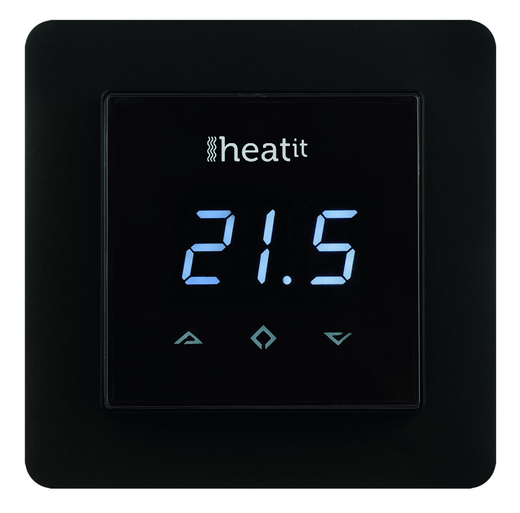
Heatit Z-Wave is an electronic thermostat for mounting in a standard wall box. The thermostat has a built-in Z-Wave chip that can be connected to Home Automation systems like Fibaro, Sensio, Vera, Zipato and others.
The display will show the actual room temperature. By pressing the buttons, the display will show the set value. Heatit Z-Wave is equipped with a single-pole switch.
The thermostat can handle loads up to 16A/3600Watt 230V. If the load is greater than this, the thermostat needs to be connected to a contactor. It can be used with two external temperature sensors.
Prepare for Installation / Reset
Please read the user manual before installing the product.
In order to include (add) a Z-Wave device to a network it must be in factory default state. Please make sure to reset the device into factory default. You can do this by performing an Exclusion operation as described below in the manual. Every Z-Wave controller is able to perform this operation however it is recommended to use the primary controller of the previous network to make sure the very device is excluded properly from this network.
Reset to factory default
This device also allows to be reset without any involvement of a Z-Wave controller. This procedure should only be used when the primary controller is inoperable.
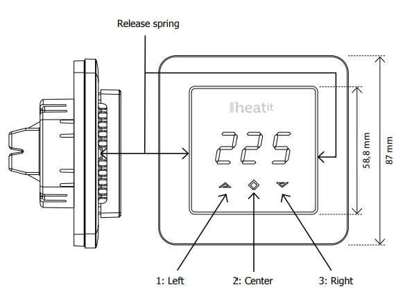
By pressing buttons Left and Center (up and confirm) for 20 seconds, the thermostat will perform a complete factory reset.
Safety Warning for Mains Powered Devices
ATTENTION: only authorized technicians under consideration of the country-specific installation guidelines/norms may do works with mains power. Prior to the assembly of the product, the voltage network has to be switched off and ensured against re-switching.
Installation
Use e.g. a small slotted screwdriver. Start by carefully removing the front cover by pushing the release springs. The front cover and the frame can now be removed.
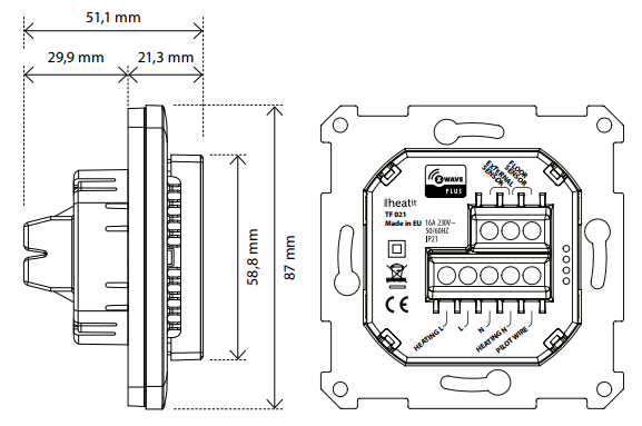
CONNECTION CLAMPS
Use 1,5 mm² or 2,5 mm² cables according to power need.
HEATING (N) Heating cable connection
(Neutral) N Power connection
(Neutral) 230V L Power connection (Live) 230V
HEATING (L) Heating cable connection (Live)
PILOT Pilot signal (ECO temp) 230V
FLOOR SENSOR NTC type (10, 12, 15, 22, 33 or 47kΩ). Default 10kΩ.
EXTERNAL SENSOR NTC type (10, 12, 15, 22, 33 or 47kΩ). Default 10kΩ.
Next, position the thermostat and fasten it onto the wall’s mounting box using 2-4 screws. Position the frame, then position and carefully press the front cover until it snaps in place. Check that the front cover has snapped in place properly on both left and right side. The front cover should now be firmly fixed on all sides.
Inclusion/Exclusion
On factory default the device does not belong to any Z-Wave network. The device needs to be added to an existing wireless network to communicate with the devices of this network. This process is called Inclusion.
Devices can also be removed from a network. This process is called Exclusion. Both processes are initiated by the primary controller of the Z-Wave network. This controller is turned into exclusion respective inclusion mode. Inclusion and Exclusion is then performed doing a special manual action right on the device.
Inclusion
Press Center (confirm) for 10 seconds. The display will show OFF. Press Right (down) 4 times till you see Con in the display. Now start add device in your home automation software. Start inclusion mode by pressing Center (confirm) for approximately 2 seconds. The inclusion/exclusion icon will appear in the display. Confirmation will show Inc/EcL in the display. If inclusion fails, Err (error) will appear.Exclusion
Press Center (confirm) for 10 seconds. The display will show OFF. Press Right (down) 4 times till you see Con in the display. Now start add device in your home automation software. Start inclusion mode by pressing Center (confirm) for approximately 2 seconds. The inclusion/exclusion icon will appear in the display. Confirmation will show Inc/EcL in the display. If inclusion fails, Err (error) will appear.Product Usage
PROGRAMMING YOUR THERMOSTAT
To activate the programming mode, press Center (confirm) for 10 seconds. Now the display will show OFF. Now you are in programming mode. To scroll up and down in the menu use button 1 and 3 (left and right) to navigate. To enter submenu press Center (confirm). Always confirm your setting by pressing Center (confirm) for 2 seconds.
Menu: OFF Turns the thermostat off.
Sensors:
A Internal room sensor
AF Internal room + Floor sensor
A2 External room sensor
P Power regulator
FP Floor sensor + Power regulator
A2F External room sensor + Floor sensor
Depending on your choice of sensors, the menu will change.
SEn Select the right Ohm value for your external/floor sensor. NTC type (10, 12, 15, 22, 33 or 47kΩ). Default 10kΩ.
CAE Calibration for external sensor.
CAF Calibration for floor sensor.
CAR Calibration for room sensor.
br1 Brightness of display can be adjusted in this menu.
Con Activation of inclusion/exclusion mode.
diF Hysteresis
ALo Setting lowest allowed temperature (limitation). (Airsensor)
AHI Setting highest allowed temperature (limitation). (Airsensor)
FLO Setting lowest allowed temperature (limitation). (Floor sensor)
FHI Setting highest allowed temperature (limitation). (Floor sensor)
HEA Switch between heating and cooling function.
ESC Escape – exit programming menu
The thermostat has a range of choices when it comes to sensors. To get to the menu you have to press Center (confirm) for 10 seconds, then press Right (down) once and an A shows in the display. Then press Center (confirm) again and you can choose one of these modes, while moving up and down with buttons Left or Right.
When you have decided on the sensor mode you want to use, press the Center (confirm) button. If you choose F or AF without having a floor sensor connected, Er4 will be shown in the display. If you choose A2 or A2F and there is no external sensor installed, Er5 will be displayed on the screen.
NOTE: Wooden floors require that a floor sensor is connected in order to limit the floor temperature to a maximum of 27°C (in accordance with specifications from most wooden floor manufacturers).
SELECT THE RIGHT OHM VALUE FOR YOUR EXTERNAL/ FLOOR SENSOR
The following values are available: NTC type (10, 12, 15, 22, 33 or 47kΩ). Default 10kΩ. The function is only active when an external sensor is connected. Confirm with Center (confirm) button.
CALIBRATION
In this mode you are able to adjust the displayed temperature. If the thermostat of some reason (or sensor) is not calibrated properly you are able to make minor changes to the temperature. You are able to raise/lower the set point by up to 4°C. Confirm with Center (confirm) button. This function is only available for the floor sensor and external room sensor. When calibrating the room sensor, only the setpoint is changed. The display will not change.
BRIGHTNESS
Use Left and Right (up and down) button to adjust the brightness between 0-9. Confirm with Center (confirm) button.
HYSTERESIS
(DIF) In this mode you are able to make changes to the hysteresis in the thermostat. This means that you can changes the hysteresis from 0.2°C up to max 3.0°C. Confirm with Center (confirm) button. Default setting is 0.5°C. When using a waterbased heating, the recommended hysteresis is a minimum of 1.0°C
STANDBY AND MAIN SCREEN
When the thermostat remains untouched for a while, it will automatically go to standby screen. Standby screen shows the temperature in the room or floor if the thermostat is connected to external sensors. By pressing Left or Right (up or down) button the setpoint will be shown in the display. If the internal room sensor is used, the thermostat display shows the setpoint.
DISPLAY ON/OFF - DON/DOF
Activate by pressing Left and Center (up and confirm) button for 10 seconds. The display light is temporarily activated if one of the buttons is pushed. In case doF is activated, the screen will be blank (can be used if installed where people are sensitive to the light of the display). A very nice feature when used in a bedroom. When touching the display, the screen lights up.
CHILDLOCK - LOC
By pressing Left and Right (up and down) buttons for 10 seconds, child lock will be activated and no changes can be made. Trying to make changes causes the LOC text to appear in the display. Child lock is deactivated by pressing Left and Right (up and down) buttons for 10 seconds. OPn will appear in the display.
CO/ECO MODE
The thermostat has 2 main programs, CO – comfort mode and ECO - economy mode. When Center (confirm) button is pushed for 2 seconds you switch between the 2 modes. You would normally have 2 different set-points for the different modes.
CO – mode: Is used for normal use. Example: 21°C.
ECO – mode: Is a setback mode that you can use if the thermostat is installed in a room or a house that is rarely used.
The ECO-mode can also be activated by the pilot wire if this is connected. Example: 18°C. Some gateways also support switching between CO/ECO mode. In most circumstances, the CO/ECO function can be regarded as a home/away function.
ERROR CODES
Er1: Internal error
Er2: Z-Wave error
Er3: Internal error
Er4: Floor sensor error
Er5: External sensor error
Quick trouble shooting
Here are a few hints for network installation if things dont work as expected.
- Make sure a device is in factory reset state before including. In doubt exclude before include.
- If inclusion still fails, check if both devices use the same frequency.
- Remove all dead devices from associations. Otherwise you will see severe delays.
- Never use sleeping battery devices without a central controller.
- Dont poll FLIRS devices.
- Make sure to have enough mains powered device to benefit from the meshing
Firmware-Update over the Air
This device is capable of receiving a new firmware 'over the air'. The update function needs to be supported by the central controller. Once the controller starts the update process, perform the following action to confirm the firmware update: Use Update Cable for update.
Association - one device controls an other device
Z-Wave devices control other Z-Wave devices. The relationship between one device controlling another device is called association. In order to control a different device, the controlling device needs to maintain a list of devices that will receive controlling commands. These lists are called association groups and they are always related to certain events (e.g. button pressed, sensor triggers, ...). In case the event happens all devices stored in the respective association group will receive the same wireless command wireless command, typically a 'Basic Set' Command.
Association Groups:
| Group Number | Maximum Nodes | Description |
|---|---|---|
| 1 | 8 | Z-Wave Plus Lifeline |
Configuration Parameters
Z-Wave products are supposed to work out of the box after inclusion, however certain configuration can adapt the function better to user needs or unlock further enhanced features.
IMPORTANT: Controllers may only allow configuring signed values. In order to set values in the range 128 ... 255 the value sent in the application shall be the desired value minus 256. For example: To set a parameter to 200 it may be needed to set a value of 200 minus 256 = minus 56. In case of a two byte value the same logic applies: Values greater than 32768 may needed to be given as negative values too.
Parameter 1: Operation mode
Size: 1 Byte, Default Value: 1
| Setting | Description |
|---|---|
| 0 | Off |
| 1 | Heat |
| 2 | Cool |
| 3 | Energy Save Heat |
Parameter 2: Sensor mode
Size: 1 Byte, Default Value: 1
| Setting | Description |
|---|---|
| 0 | F-Mode |
| 1 | A-Mode |
| 2 | AF-Mode |
| 3 | A2-Mode |
| 4 | P-Mode |
| 5 | FP-Mode |
Parameter 3: Floor sensor type
Size: 1 Byte, Default Value: 0
| Setting | Description |
|---|---|
| 0 | 10K NTC |
| 1 | 12K NTC |
| 2 | 15K NTC |
| 3 | 22K NTC |
| 4 | 33K NTC |
| 5 | 47K NTC |
Parameter 4: DIFF l. Temperature control Hysteresis
Size: 2 Byte, Default Value: 5
| Setting | Description |
|---|---|
| 3 - 30 | 0,3°C - 3°C |
Parameter 5: FLo, Floor min limit
Size: 2 Byte, Default Value: 50
| Setting | Description |
|---|---|
| 50 - 400 | 5°C - 40°C |
Parameter 6: FHi, Floor max limit
Size: 2 Byte, Default Value: 400
| Setting | Description |
|---|---|
| 50 - 400 | 5°C - 40°C |
Parameter 7: ALo, Air min limit
Size: 2 Byte, Default Value: 50
| Setting | Description |
|---|---|
| 50 - 400 | 5°C - 40°C |
Parameter 8: AHi, Air max limit
Size: 2 Byte, Default Value: 400
| Setting | Description |
|---|---|
| 50 - 400 | 5°C - 40°C |
Parameter 9: PLo, FP-mode P setting
Size: 1 Byte, Default Value: 0
| Setting | Description |
|---|---|
| 0 - 9 | Value |
Parameter 10: CO mode setpoint
Size: 2 Byte, Default Value: 210
| Setting | Description |
|---|---|
| 50 - 400 | 5°C - 40°C |
Parameter 11: ECO mode setpoint
Size: 2 Byte, Default Value: 180
| Setting | Description |
|---|---|
| 50 - 400 | 5°C - 40°C |
Parameter 12: P setting
Size: 1 Byte, Default Value: 2
| Setting | Description |
|---|---|
| 0 - 10 | Value |
Parameter 13: COOL setpoint
Size: 2 Byte, Default Value: 210
| Setting | Description |
|---|---|
| 50 - 400 | 5°C - 40°C |
Technical Data
| Dimensions | 85x85x50 mm |
| Weight | 109 gr |
| Hardware Platform | ZM5202 |
| EAN | 7071236011927 |
| IP Class | IP 20 |
| Voltage | 230 V |
| Load | 16A |
| Device Type | Thermostat - HVAC |
| Network Operation | Always On Slave |
| Z-Wave Version | 6.51.00 |
| Certification ID | ZC10-15020003 |
| Z-Wave Product Id | 0x019B.0x0001.0x0001 |
| Frequency | Europe - 868,4 Mhz |
| Maximum transmission power | 5 mW |
Supported Command Classes
- Association
- Association Group Information
- Basic
- Device Reset Locally
- Manufacturer Specific
- Sensor Multilevel
- Powerlevel
- Thermostat Mode
- Thermostat Setpoint
- Version
- Zwaveplus Info
Controlled Command Classes
- Basic
Explanation of Z-Wave specific terms
- Controller — is a Z-Wave device with capabilities to manage the network. Controllers are typically Gateways,Remote Controls or battery operated wall controllers.
- Slave — is a Z-Wave device without capabilities to manage the network. Slaves can be sensors, actuators and even remote controls.
- Primary Controller — is the central organizer of the network. It must be a controller. There can be only one primary controller in a Z-Wave network.
- Inclusion — is the process of adding new Z-Wave devices into a network.
- Exclusion — is the process of removing Z-Wave devices from the network.
- Association — is a control relationship between a controlling device and a controlled device.
- Wakeup Notification — is a special wireless message issued by a Z-Wave device to announces that is able to communicate.
- Node Information Frame — is a special wireless message issued by a Z-Wave device to announce its capabilities and functions.