Hank
Scene Controller
SKU: HNKESCN04


Quickstart
This is a
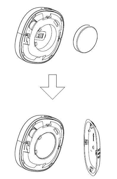
1. Insert the LIR2450 battery.
2. Set the Z-Wave network main controller into learning mode( see Z-Waave network controller operating manul).
3. Triple click a button. 4. If the inclusion is successful, the LED will blink in blue less than for 5 seconds and then keep on for 15 seconds.
Important safety information
Please read this manual carefully. Failure to follow the recommendations in this manual may be dangerous or may violate the law. The manufacturer, importer, distributor and seller shall not be liable for any loss or damage resulting from failure to comply with the instructions in this manual or any other material. Use this equipment only for its intended purpose. Follow the disposal instructions. Do not dispose of electronic equipment or batteries in a fire or near open heat sources.Product Description
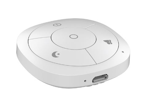
The Scene Controller is a wireless, portable and rechargeable scene switch. It can control a Z-Wave device, such as smart plug, smart dimmer with a Z-Wave gateway. You can also activate a scene like sleep scene, movie scene and entertainment scene with it.
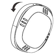
Installation
Open the cover, as the figure beows shows.
Insert your battery and close the cover, as the figure below shows.
Product Usage
| Reset to factory default | Pressing and holding a button for 20 seconds. Release the button after 20 seconds, LED will keep in yellow for 3 seconds. Scene Controller will be reset to factory defaults if you short press the button within this 3 seconds. Using this procedure only in the event that the network primary controller is missing or otherwise inoperable. |
| Inclusion | Unsecure: - Triple click a button. Secure: - Pressing and holding a button for 3 seconds. |
| Exclusion | Triple click the a button, if the exclusion is successful, LED will blink in orange for less than 5 seconds and then keep on for 3 seconds. |
| NIF | XXXNIF |
| Wakeup | Pressing and holding a button for 3 seconds. Led will turn to green, which means Scene Controller has been woken up. |
| Protection | XXXProtection |
| FirmwareUpdate | XXXFirmwareUpdate |
| SetAssociation | XXXSetAssociation |
Association Groups:
| Group Number | Maximum Nodes | Description |
|---|---|---|
| 1 | 5 | Scene Controller will send the central scene notification command and battery report command to the associated nodes if any button is triggered. |
| 2 | 5 | Scene Controller will send Basic Set command to the associated nodes if button 1 is pressed. |
| 3 | 5 | Scene Controller will send switch multilevel set, the multilevel start level change and multilevel stop level change command to the associated nodes if button 1 is pressed, hold and released, respectively. |
| 4 | 5 | Scene Controller will send Basic Set command to the associated nodes if button 2 is pressed. |
| 5 | 5 | Scene Controller will send switch multilevel set, the multilevel start level change and multilevel stop level change command to the associated nodes if button 2 is pressed, hold and released, respectively. |
| 6 | 5 | Scene Controller will send Basic Set command to the associated nodes if button 3 is pressed. |
| 7 | 5 | Scene Controller will send switch multilevel set, the multilevel start level change and multilevel stop level change command to the associated nodes if button 3 is pressed, hold and released, respectively. |
| 8 | 5 | Scene Controller will send Basic Set command to the associated nodes if button 4 is pressed. |
| 9 | 5 | Scene Controller will send switch multilevel set, the multilevel start level change and multilevel stop level change command to the associated nodes if button 4 is pressed, hold and released, respectively. |
Configuration Parameters
Parameter 254: Enable/disable the configuration command
Lock/unlock all configuration parameters. Size: 1 Byte, Default Value: 0
| Setting | Description |
|---|---|
| 0 | Unlock all configuration parameters. |
| 1 | Lock all configuration parameters |
Parameter 255: Reset Scene Controller
Reset Scene Controller and remove from the Z-Wave network Size: 4 Byte, Default Value: 0
| Setting | Description |
|---|---|
| 1431655765 | Reset Scene Controller and remove from the Z-Wave network |
Technical Data
| Dimensions | 50 x 16 mm |
| Weight | 19 gr |
| Hardware Platform | ZM5101 |
| EAN | 6925312929082 |
| IP Class | IP 20 |
| Voltage | 3,6V |
| Battery Type | 1 * LIR2450 |
| Device Type | Wall Controller |
| Network Operation | Portable Slave |
| Z-Wave Version | 6.51.08 |
| Certification ID | ZC10-16095219 |
| Z-Wave Product Id | 0x0208.0x0200.0x000B |
| Z-Wave Scene Type | Central Scene |
| Frequency | Europe - 868,4 Mhz |
| Maximum transmission power | 5 mW |