MCO Home
Shutter Panel Switch UK
SKU: MCOEC321

Quickstart
This is a
Important safety information
Please read this manual carefully. Failure to follow the recommendations in this manual may be dangerous or may violate the law. The manufacturer, importer, distributor and seller shall not be liable for any loss or damage resulting from failure to comply with the instructions in this manual or any other material. Use this equipment only for its intended purpose. Follow the disposal instructions. Do not dispose of electronic equipment or batteries in a fire or near open heat sources.Product Description
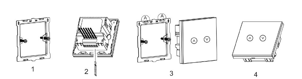
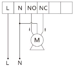
Installation
Product Usage
1. A demo trip which help to read motor data will start as follow:
| Reset to factory default | Press 10 times of UP or DOWN button or exclude the device from Z-Wave network, then cut off the main power. The factory setting will be restored. |
| Inclusion | 1. Power the panel on, if LEDs flick 4 times, it shows the device is not in any Z-Wave network. If LEDs turns to orange directly, the panel is in a network already.
2. Set controller into Include/Exclude mode, and press 8 seconds or 3 clicks on "UP" or "DOWN" button to add/remove. If succeed, green LED flicks 4 times. |
| Exclusion | 1. Power the panel on, if LEDs flick 4 times, it shows the device is not in any Z-Wave network. If LEDs turns to orange directly, the panel is in a network already.
2. Set controller into Include/Exclude mode, and press 8 seconds or 3 clicks on "UP" or "DOWN" button to add/remove. If succeed, green LED flicks 4 times. |
| NIF | XXXNIF |
| Wakeup | XXXWakeupDescription |
| Protection | XXXProtection |
| FirmwareUpdate | XXXFirmwareUpdate |
| SetAssociation | XXXSetAssociation |
Association Groups:
| Group Number | Maximum Nodes | Description |
|---|---|---|
| 1 | 1 | Lifeline |
Configuration Parameters
Parameter 1: Watt Meter Report period
Size: 2 Byte, Default Value: 720
| Setting | Description |
|---|---|
| 1 - 32767 | Unit 5sec 5*720S=3600S= 1hour |
Parameter 2: KWH Meter Report period
Size: 2 Byte, Default Value: 6
| Setting | Description |
|---|---|
| 1 - 32767 | Unit 10min 6*10min=1 hour |
Parameter 5: Level Report Mode
Size: 1 Byte, Default Value: 2
| Setting | Description |
|---|---|
| 1 | Report destination level in 5s period when requested by the gateway; And then report current level after 5s. |
| 2 | Report every 10% level change while running |
Parameter 7: Demo trip
Size: 1 Byte, Default Value: 0
| Setting | Description |
|---|---|
| 1 | activate demo trip only |
Parameter 8: LED Backlit brightness level
Size: 1 Byte, Default Value: 10
| Setting | Description |
|---|---|
| 0 | LED disabled |
| 1 - 10 | Min level-Max level |
| 11 - 255 | same level as 10 |
Parameter 9: Demo trip and calibration
Size: 1 Byte, Default Value: 0
| Setting | Description |
|---|---|
| 1 | activate demo trip and calibration |
Parameter 10: Auto calibration
Size: 1 Byte, Default Value: 0
| Setting | Description |
|---|---|
| 1 | activate calibration |
Parameter 11: Min level of the shutter close
Size: 1 Byte, Default Value: 0
| Setting | Description |
|---|---|
| 0 - 98 | in % |
Parameter 1: Max level of the shutter open
Size: 1 Byte, Default Value: 99
| Setting | Description |
|---|---|
| 1 - 99 | in % |
Parameter 255: Factory setting
Size: 1 Byte, Default Value: 0
| Setting | Description |
|---|---|
| 85 | Factory Reset |
Technical Data
| Dimensions | 0.0860000x0.0860000x0.0420000 mm |
| Weight | 163 gr |
| Hardware Platform | ZM5202 |
| EAN | 6928954214004 |
| IP Class | IP 20 |
| Voltage | 230 V |
| Load | 2x 3,5 A |
| Device Type | Window Covering Position/Endpoint Aware |
| Generic Device Class | Multilevel Switch |
| Specific Device Class | Motor Control Device (C) |
| Firmware Version | 03.02 |
| Z-Wave Version | 04.3e |
| Z-Wave Product Id | 0x015f.0xc321.0x5102 |
| Frequency | Europe - 868,4 Mhz |
| Maximum transmission power | 5 mW |