MCO Home
MCO Home - Water Heating Thermostat with humidity sensor Version 2
SKU: MCOEMH7H-WH2

Quickstart
This is a
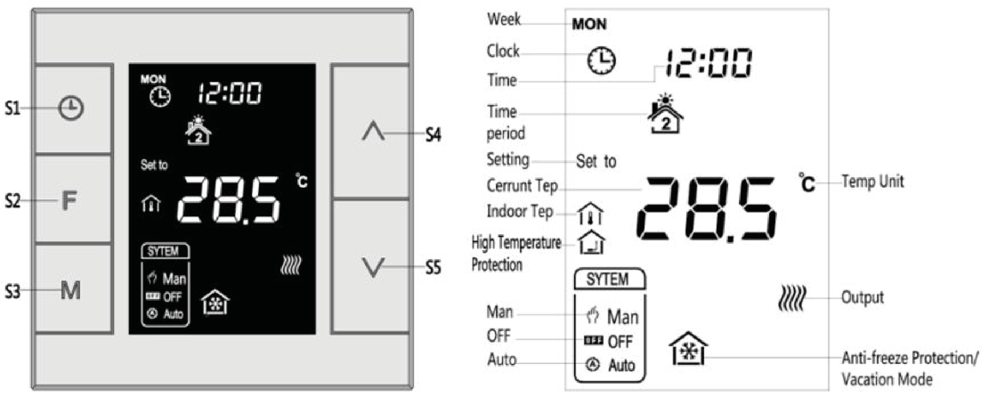
In normal working interface, press & hold S4 to enter interface for inclusion of Z-Wave network. Before device included into network, “- - -” will display on the screen. Then press S4 once, device will enter learning mode to get a node ID. If inclusion is success, a node ID will display on the screen in a few seconds.
Important safety information
Please read this manual carefully. Failure to follow the recommendations in this manual may be dangerous or may violate the law. The manufacturer, importer, distributor and seller shall not be liable for any loss or damage resulting from failure to comply with the instructions in this manual or any other material. Use this equipment only for its intended purpose. Follow the disposal instructions. Do not dispose of electronic equipment or batteries in a fire or near open heat sources.What is Z-Wave?
Z-Wave is the international wireless protocol for communication in the Smart Home. This device is suited for use in the region mentioned in the Quickstart section.
Z-Wave ensures a reliable communication by reconfirming every message (two-way communication) and every mains powered node can act as a repeater for other nodes (meshed network) in case the receiver is not in direct wireless range of the transmitter.
This device and every other certified Z-Wave device can be used together with any other certified Z-Wave device regardless of brand and origin as long as both are suited for the same frequency range.
If a device supports secure communication it will communicate with other devices secure as long as this device provides the same or a higher level of security. Otherwise it will automatically turn into a lower level of security to maintain backward compatibility.
For more information about Z-Wave technology, devices, white papers etc. please refer to www.z-wave.info.
Product Description
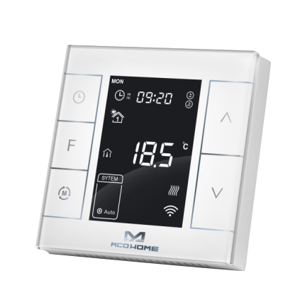
MCOHome Water Heating Thermostat is a Z-Wave enabled device for indoor temperature control. MH7H-WH is mainly applied to control wall mounted boiler, water valve/pump etc. The device is of high reliability and practicability, which can be included and operated in any Z-Wave network with other Z-Wave certified devices from any other manufacturers.
Prepare for Installation / Reset
Please read the user manual before installing the product.
In order to include (add) a Z-Wave device to a network it must be in factory default state. Please make sure to reset the device into factory default. You can do this by performing an Exclusion operation as described below in the manual. Every Z-Wave controller is able to perform this operation however it is recommended to use the primary controller of the previous network to make sure the very device is excluded properly from this network.
Safety Warning for Mains Powered Devices
ATTENTION: only authorized technicians under consideration of the country-specific installation guidelines/norms may do works with mains power. Prior to the assembly of the product, the voltage network has to be switched off and ensured against re-switching.
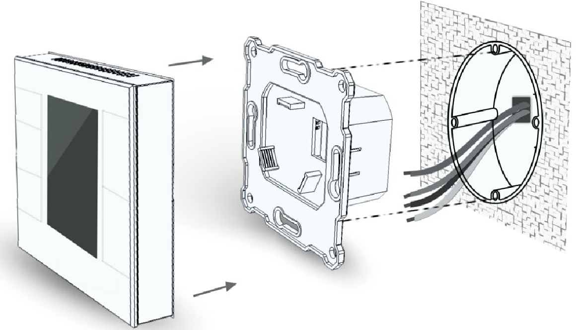
Installation
Inclusion/Exclusion
On factory default the device does not belong to any Z-Wave network. The device needs to be added to an existing wireless network to communicate with the devices of this network. This process is called Inclusion.
Devices can also be removed from a network. This process is called Exclusion. Both processes are initiated by the primary controller of the Z-Wave network. This controller is turned into exclusion respective inclusion mode. Inclusion and Exclusion is then performed doing a special manual action right on the device.
Inclusion
In normal working interface, press & hold S4 to enter interface for inclusion of Z-Wave network. Before device included into network, “- - -” will display on the screen. Then press S4 once, device will enter learning mode to get a node ID. If inclusion is success, a node ID will display on the screen in a few seconds.Exclusion
Auto-Inclusion
Beside the standard inclusion this devices supports the so called auto inclusion. Right after powering up the device remains in inclusion state and can be included by (any) gateway without further actions on the device itself. The auto inclusion mode will time out after some time.Product Usage
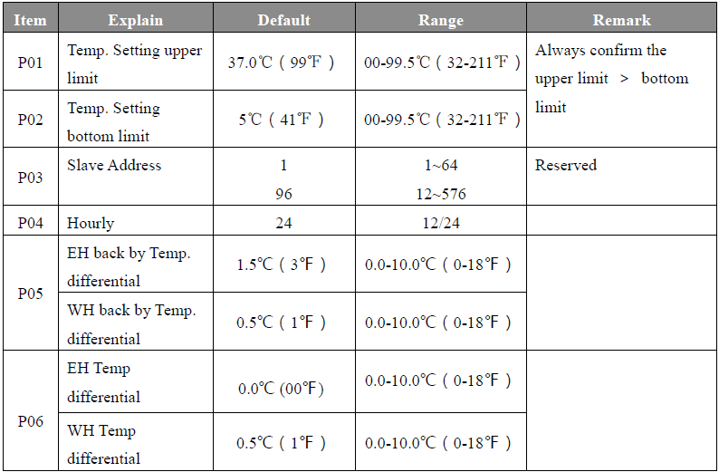
Control specifications
- Detection temperature ≥ setting temperature + 0.5℃, output turns off, and output icon disappears.
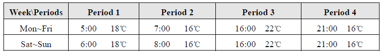
Manual / Auto mode setting
In normal display interface, touch S3 button can switch between Manual and Auto mode.
The default setting is as follow:
Note: If MH7 thermostat do not connect with an external temperature sensor, it will only display the indoor temperature icon; If MH7 thermostat connect with an external temperature sensor, it will display the indoor temperature and high temperature protection icon; When it is under high temperature protection, high temperature protection icon flickers.
Quick trouble shooting
Here are a few hints for network installation if things dont work as expected.
- Make sure a device is in factory reset state before including. In doubt exclude before include.
- If inclusion still fails, check if both devices use the same frequency.
- Remove all dead devices from associations. Otherwise you will see severe delays.
- Never use sleeping battery devices without a central controller.
- Dont poll FLIRS devices.
- Make sure to have enough mains powered device to benefit from the meshing
Association - one device controls an other device
Z-Wave devices control other Z-Wave devices. The relationship between one device controlling another device is called association. In order to control a different device, the controlling device needs to maintain a list of devices that will receive controlling commands. These lists are called association groups and they are always related to certain events (e.g. button pressed, sensor triggers, ...). In case the event happens all devices stored in the respective association group will receive the same wireless command wireless command, typically a 'Basic Set' Command.
Association Groups:
| Group Number | Maximum Nodes | Description |
|---|---|---|
| 1 | 1 | Lifeline |
| 2 | 5 | Switching relays |
| 3 | 5 | Switching relays |
Configuration Parameters
Z-Wave products are supposed to work out of the box after inclusion, however certain configuration can adapt the function better to user needs or unlock further enhanced features.
IMPORTANT: Controllers may only allow configuring signed values. In order to set values in the range 128 ... 255 the value sent in the application shall be the desired value minus 256. For example: To set a parameter to 200 it may be needed to set a value of 200 minus 256 = minus 56. In case of a two byte value the same logic applies: Values greater than 32768 may needed to be given as negative values too.
Parameter 1: Upload temperature format automatically
Size: 1 Byte, Default Value: 2
| Setting | Description |
|---|---|
| 0 | Celsius |
| 1 | Fahrenheit |
| 2 | Follow the main display |
Parameter 2: Upload temperature and humidity automatically
Size: 1 Byte, Default Value: 3
| Setting | Description |
|---|---|
| 0 | OFF |
| 1 | Upload the difference value only |
| 2 | Timing upload mode only |
| 3 | Upload the difference+timing upload mode |
Parameter 3: Upload temperature difference
Size: 2 Byte, Default Value: 5
| Setting | Description |
|---|---|
| 3 - 1000 | 5*0.1℃=0.5℃, steps 0,1 |
Parameter 4: Upload time interval regularly
Size: 2 Byte, Default Value: 30
| Setting | Description |
|---|---|
| 10 - 65535 | in seconds |
Parameter 5: Upload humidity difference
When the detection humidity value differ with the last percentage value, uploading activated 2-255 Size: 2 Byte, Default Value: 3
| Setting | Description |
|---|---|
| 2 - 255 | in % |
Parameter 255: Factory setting
Size: 1 Byte, Default Value: 0
| Setting | Description |
|---|---|
| 85 | Reset |
Technical Data
| Dimensions | 86x86x42 mm |
| Weight | 190 gr |
| Hardware Platform | ZM5101 |
| EAN | 692895420707 |
| IP Class | IP 20 |
| Voltage | 230 V |
| Load | 5a |
| Device Type | Thermostat |
| Firmware Version | 02.06 |
| Z-Wave Version | 04.21 |
| Certification ID | ZC10-18046084 |
| Z-Wave Product Id | 0x015f.0x0712.0x5102 |
| Frequency | Europe - 868,4 Mhz |
| Maximum transmission power | 5 mW |
Supported Command Classes
- Basic
- Sensor Multilevel
- Thermostat Mode
- Thermostat Operating State
- Thermostat Setpoint
- Association Grp Info
- Device Reset Locally
- Zwaveplus Info
- Configuration
- Manufacturer Specific
- Powerlevel
- Firmware Update Md
- Association
- Version
- Time
- Time Parameters
Explanation of Z-Wave specific terms
- Controller — is a Z-Wave device with capabilities to manage the network. Controllers are typically Gateways,Remote Controls or battery operated wall controllers.
- Slave — is a Z-Wave device without capabilities to manage the network. Slaves can be sensors, actuators and even remote controls.
- Primary Controller — is the central organizer of the network. It must be a controller. There can be only one primary controller in a Z-Wave network.
- Inclusion — is the process of adding new Z-Wave devices into a network.
- Exclusion — is the process of removing Z-Wave devices from the network.
- Association — is a control relationship between a controlling device and a controlled device.
- Wakeup Notification — is a special wireless message issued by a Z-Wave device to announces that is able to communicate.
- Node Information Frame — is a special wireless message issued by a Z-Wave device to announce its capabilities and functions.