Philio Tech
Z-Wave Smart Dimmer Socket
SKU: PHIEPAD02


Quickstart
This is a
2. Pressing Include button of PAD02 three times within 2 seconds will enter inclusion mode.
Important safety information
Please read this manual carefully. Failure to follow the recommendations in this manual may be dangerous or may violate the law. The manufacturer, importer, distributor and seller shall not be liable for any loss or damage resulting from failure to comply with the instructions in this manual or any other material. Use this equipment only for its intended purpose. Follow the disposal instructions. Do not dispose of electronic equipment or batteries in a fire or near open heat sources.What is Z-Wave?
Z-Wave is the international wireless protocol for communication in the Smart Home. This device is suited for use in the region mentioned in the Quickstart section.
Z-Wave ensures a reliable communication by reconfirming every message (two-way communication) and every mains powered node can act as a repeater for other nodes (meshed network) in case the receiver is not in direct wireless range of the transmitter.
This device and every other certified Z-Wave device can be used together with any other certified Z-Wave device regardless of brand and origin as long as both are suited for the same frequency range.
If a device supports secure communication it will communicate with other devices secure as long as this device provides the same or a higher level of security. Otherwise it will automatically turn into a lower level of security to maintain backward compatibility.
For more information about Z-Wave technology, devices, white papers etc. please refer to www.z-wave.info.
Product Description
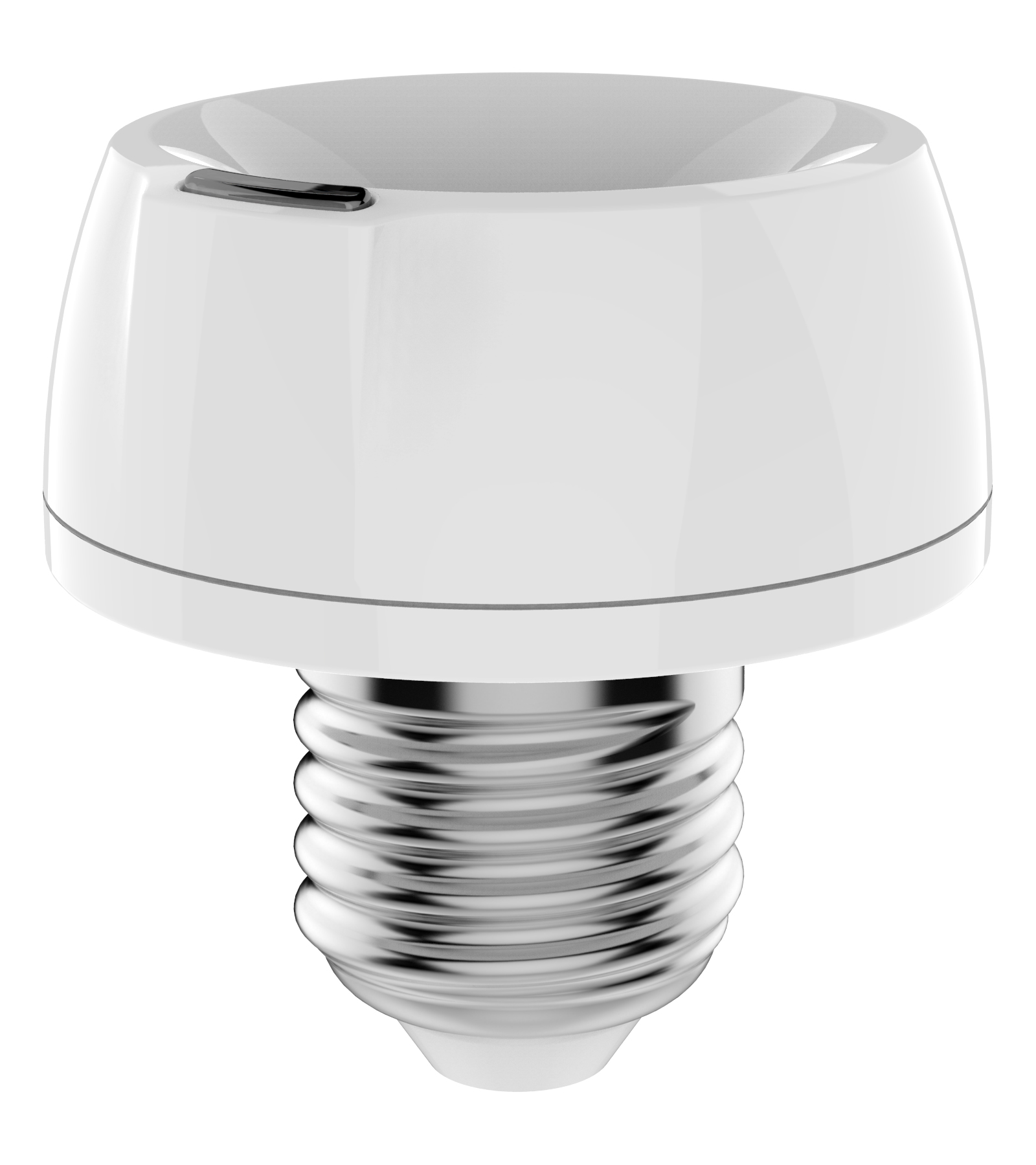
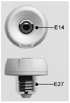
PAD02 is an E27(EU)/ E26(US) Edison screw based lamp socket, which provides electrical connection to the E14(EU)/ E12(US) Edison screw based lamps and support it in the lighting fixture. The use of socket allows lamps to be safely and conveniently replaced. You can On/Off the light by pressing the button briefly or a long pressing to control the brightness of dimmable lightbulb. This dimmer is a transceiver which is a security enabled device which based on Z-Wave Plus technology. Z-Wave Plus enabled devices displaying the Z-Wave Plus logo can also be used with it regardless of the manufacturer and can also be used in other manufacturers Z- Wave enabled networks. Remote dim level control of the connected light is possible with other manufacturers wireless Controller. Since PAD02 supports Security Command Class, it can learn with a Secured enabled controller to fully utilize the device. Its functionality and supported command classes is identical when included as a secure and non-secure device. Adding to Z- Wave Network In the front casing, there is an on/off button with LED indicator below which is used to switch on and off, dim level, or carries out add, remove, reset or association. When first power is applied, its LED flashes on and off alternately and repeatedly at 0.5 second intervals. It implies that it has not been assigned a node ID and start auto inclusion. Auto Inclusion The function of auto inclusion will be executed as long as the dimmer does not have Node ID and just connect the dimmer to main power. Note: Auto inclusion timeout is 2 minute during which the node information of explorer frame will be emitted once every several seconds. Unlike inclusion function as shown in the table below, the execution of auto inclusion is free from pressing the On/Off button on the dimmer.
Prepare for Installation / Reset
Please read the user manual before installing the product.
In order to include (add) a Z-Wave device to a network it must be in factory default state. Please make sure to reset the device into factory default. You can do this by performing an Exclusion operation as described below in the manual. Every Z-Wave controller is able to perform this operation however it is recommended to use the primary controller of the previous network to make sure the very device is excluded properly from this network.
Reset to factory default
This device also allows to be reset without any involvement of a Z-Wave controller. This procedure should only be used when the primary controller is inoperable.
1. Pressing Include button of PAD02 three times within 2 seconds will enter inclusion mode.
2. Within 1 second, press Include button of PAD02 again for 5 seconds.
3. IDs are excluded.
Safety Warning for Mains Powered Devices
ATTENTION: only authorized technicians under consideration of the country-specific installation guidelines/norms may do works with mains power. Prior to the assembly of the product, the voltage network has to be switched off and ensured against re-switching.
Inclusion/Exclusion
On factory default the device does not belong to any Z-Wave network. The device needs to be added to an existing wireless network to communicate with the devices of this network. This process is called Inclusion.
Devices can also be removed from a network. This process is called Exclusion. Both processes are initiated by the primary controller of the Z-Wave network. This controller is turned into exclusion respective inclusion mode. Inclusion and Exclusion is then performed doing a special manual action right on the device.
Inclusion
Pressing Include button of PAD02 three times within 2 seconds will enter inclusion mode.Exclusion
Pressing Include button of PAD02 three times within 2 seconds will enter exclusion mode.Auto-Inclusion
Beside the standard inclusion this devices supports the so called auto inclusion. Right after powering up the device remains in inclusion state and can be included by (any) gateway without further actions on the device itself. The auto inclusion mode will time out after some time.Product Usage
Normal - Whenever we switch On and off of the PAD02 by On/Off button or RF command, the LED will lights up when switch on; whereas LED off when switch off.
No node ID - Under normal operation, when the dimmer has not been allocated a node ID, the LED flashes on and off alternately at 2-second intervals. By pressing On/Off button, it will stop flashing temporarily.
Learning - When PAD02 is in learning mode, LED flashes on and off alternately and repeatedly at 0.5 second intervals.
Quick trouble shooting
Here are a few hints for network installation if things dont work as expected.
- Make sure a device is in factory reset state before including. In doubt exclude before include.
- If inclusion still fails, check if both devices use the same frequency.
- Remove all dead devices from associations. Otherwise you will see severe delays.
- Never use sleeping battery devices without a central controller.
- Dont poll FLIRS devices.
- Make sure to have enough mains powered device to benefit from the meshing
Association - one device controls an other device
Z-Wave devices control other Z-Wave devices. The relationship between one device controlling another device is called association. In order to control a different device, the controlling device needs to maintain a list of devices that will receive controlling commands. These lists are called association groups and they are always related to certain events (e.g. button pressed, sensor triggers, ...). In case the event happens all devices stored in the respective association group will receive the same wireless command wireless command, typically a 'Basic Set' Command.
Association Groups:
| Group Number | Maximum Nodes | Description |
|---|---|---|
| 1 | 5 | Lifeline - The dimmer can be set to send reports to associated Z-Wave devices. It supports one association group with one node support for Grouping 1. For group 1, the dimmer will report ALARM_REPORT,DEVICE_RESET_LOCALLY_NOTIFICATION and MULTILEVEL_SWITCH_REPORT. |
| 2 | 5 | When the On/Off status changes or the dim level is achieved manually, it will send BASIC_SET command to group 2 nodes to make them unanimous. |
Configuration Parameters
Z-Wave products are supposed to work out of the box after inclusion, however certain configuration can adapt the function better to user needs or unlock further enhanced features.
IMPORTANT: Controllers may only allow configuring signed values. In order to set values in the range 128 ... 255 the value sent in the application shall be the desired value minus 256. For example: To set a parameter to 200 it may be needed to set a value of 200 minus 256 = minus 56. In case of a two byte value the same logic applies: Values greater than 32768 may needed to be given as negative values too.
Parameter 1: Dimmer Level Report mode
Whenever dimmer on/off state changes, it will send MULTILEVEL_SWITCH_REPORT to the nodes of group1. The default setting is Enable the function. Size: 1 Byte, Default Value: 1
| Setting | Description |
|---|---|
| 0 | Disable |
| 1 | Show dimmer state |
Parameter 2: LED indication mode
1. Show dimmer Stateuff1aWhen dimmer is on, LED is on. When dimmer is off, LED is off. The default setting is Show dimmer State. 2. Show Night modeuff1aWhen dimmer is on, LED is off. When dimmer is off, LED is on. 3. One flash mode : When dimmer on/off state changes, LED will light on one second and then off. Size: 1 Byte, Default Value: 1
| Setting | Description |
|---|---|
| 1 | Show dimmer state |
| 2 | Show night mode |
| 3 | One flash mode |
Parameter 4: Restore dimmer state
Whenever the AC power return from lost, PAD02 will restore the switch state which could be Dimmer offu3001Last dimmer stateu3001Dimmer on. The default setting is Last dimmer state. Size: 1 Byte, Default Value: 1
| Setting | Description |
|---|---|
| 0 | Dimmer off |
| 1 | Last dimmer state |
| 2 | Dimmer on |
Technical Data
| Dimensions | 0.0680000x0.0830000x0.0270000 mm |
| Weight | 51 gr |
| Hardware Platform | SD3502 |
| EAN | 4713698574406 |
| IP Class | IP 20 |
| Voltage | 230V |
| Load | 2A |
| Device Type | Light Dimmer Socket |
| Network Operation | Always On Slave |
| Z-Wave Version | 6.51.09 |
| Certification ID | ZC10-17045556 |
| Z-Wave Product Id | 0x013C.0x0005.0x0031 |
| Z-Wave Scene Type | Scene |
| Color | White |
| Firmware Updatable | Updatable by Consumer by RF |
| Neutral Wire Required | ok |
| Frequency | Europe - 868,4 Mhz |
| Maximum transmission power | 5 mW |
Supported Command Classes
- Alarm
- Association Grp Info
- Association V2
- Basic
- Configuration
- Device Reset Locally
- Firmware Update Md V2
- Manufacturer Specific V2
- Powerlevel
- Scene Activation
- Scene Actuator Conf
- Security
- Switch Multilevel V2
- Version V2
- Zwaveplus Info V2
Controlled Command Classes
- Basic
Explanation of Z-Wave specific terms
- Controller — is a Z-Wave device with capabilities to manage the network. Controllers are typically Gateways,Remote Controls or battery operated wall controllers.
- Slave — is a Z-Wave device without capabilities to manage the network. Slaves can be sensors, actuators and even remote controls.
- Primary Controller — is the central organizer of the network. It must be a controller. There can be only one primary controller in a Z-Wave network.
- Inclusion — is the process of adding new Z-Wave devices into a network.
- Exclusion — is the process of removing Z-Wave devices from the network.
- Association — is a control relationship between a controlling device and a controlled device.
- Wakeup Notification — is a special wireless message issued by a Z-Wave device to announces that is able to communicate.
- Node Information Frame — is a special wireless message issued by a Z-Wave device to announce its capabilities and functions.