Philio Tech
Relay Insert 2 * 1.5 KW with Power Meter
SKU: PHIEPAN04-1B

Quickstart
This is a
Important safety information
Please read this manual carefully. Failure to follow the recommendations in this manual may be dangerous or may violate the law. The manufacturer, importer, distributor and seller shall not be liable for any loss or damage resulting from failure to comply with the instructions in this manual or any other material. Use this equipment only for its intended purpose. Follow the disposal instructions. Do not dispose of electronic equipment or batteries in a fire or near open heat sources.Product Description
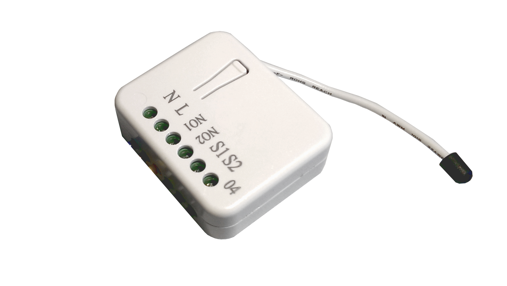
This in-wall dual relay switch module is a transceiver which is a Z-Wave Plusâ„¢ enabled device and is fully compatible with any Z-Waveâ„¢ enabled network. Mini size design let the module can easily hide itself into the wall box and that will be good for the house decoration. There are many kind of application by using the module to switch AC power On and Off, one main application is the light control. The new smart relay calibration technology can reduce the inrush current caused by the load and let the module work perfectly with many kind of light like incandescent, fluorescent and LED light.
This in-wall switch module is able to detect Instant power wattage and overload current (7.5A) of connected light or appliances. When detecting overload state, the Module will be disabled and its On/Off button will be lockout of which LED will flash quickly. However, disconnect and re-connect the Module will reset its overload condition to normal status.
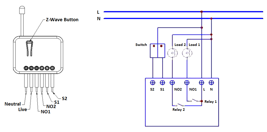
Installation
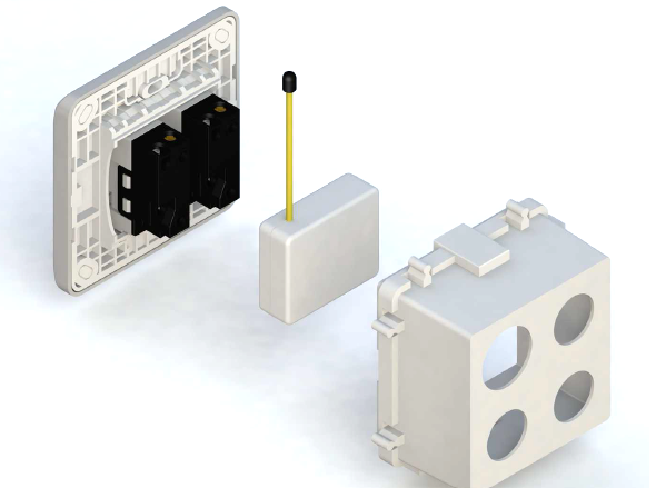
Put the in-wall switch into a wall box and connect the pins as shown in the figure.
Product Usage
Manual Operation
The device can be operated suing the externally connected switch. Three different modes are supported:
- Edge Mode: Die Position of the external switch determines the switching state of the relay. After a wireless switching command it may be needed to operate the switch twice to return to the direct relation of switch position and relay state. This mode is the factory default mode.
- Toogle Mode: Each "ON"-Position of the external switch will toggle the state of the relays. This mode is particularly suited for mono-stable switches.
- Edge/Toggle-Mode: Every change of the state of the external switch results in a change of the relay state.
Remote Operation
Remote On/Off control of the switch is possible with any Z-Wave controller. Further, you can set associations to let your device controlled by other Z-Wave devices like sensors.
The switch is able to detect the current wattage (5 - 1500W) and overload wattage (1600 - 1700W) of connected loads. When detecting an overload state, the switch will be disabled and the LED will flash quickly. Turning off and on of the power supply will reset from this state.
| Reset to factory default | Tripple Click the button on the device to enter inclusion mode. Within 1 second press the button again for 5 seconds until LED is off. |
| Inclusion | Tripple Click the button on the device confirms inclusion and exclusion. After power-up, it will stay in auto inclusion mode for 4 minutes. |
| Exclusion | Tripple Click the button on the device confirms inclusion and exclusion. After power up it will stay in auto inclusion mode for 4 minutes. |
| NIF | Tripple Click the button on the device sends out a Node Information Frame. |
| Wakeup | XXXWakeupDescription |
| Protection | XXXProtection |
| FirmwareUpdate | XXXFirmwareUpdate |
| SetAssociation | XXXSetAssociation |
Association Groups:
| Group Number | Maximum Nodes | Description |
|---|---|---|
| 1 | 1 | Status-Update for Relais 1 and 2 and all Metering reports |
| 2 | 1 | Status-Update for Relais 1 and Metering reports |
| 3 | 1 | Status-Update for Relais 2 and Metering reports |
Configuration Parameters
Parameter 1: Watt Meter Report Period
If the setting is configured for 1hour (set value =720), the PAN04 will report its instant power consumption every 1 hour to the node of correspond Group. Size: 2 Byte, Default Value: 02d0
| Setting | Description |
|---|
Parameter 2: KWH Meter Report Period
If the setting is configured for 1hour (set value =6), the PAN04 will report its Size: 2 Byte, Default Value: 0006
| Setting | Description |
|---|
Parameter 3: Selected Relay
If Controller not using Multi_Channel command class to access the relay ofPAN04, you may configure the select value to react the Basic CommandClass, Binary Switch Command Class or Meter Command Class V3. Size: 1 Byte, Default Value: 03
| Setting | Description |
|---|---|
| 01 | Relay1 |
| 02 | Relay2 |
| 03 | Relay1 & Relay2 |
Parameter 4: Edge or Pulse mode or Edge-Toggle mode
Manual switch S1 and S2 can set to Edge mode or Pulse mode or Edge-Toggle Size: 1 Byte, Default Value: 01
| Setting | Description |
|---|---|
| 01 | Edge mode |
| 02 | Pulse mode |
| 03 | Edge-Togglemode |
Parameter 5: Threshold of current for Load Caution
This is a warning when the current of load over the preset threshold value, if thesetting value is 750, when the load current of Relay1 or Relay2 over this value,PAN04 will send current meter report to the node of correspond Group, theRange of the setting value is from 10 to 750, and the default value is 750. Size: 2 Byte, Default Value: 02ee
| Setting | Description |
|---|
Parameter 6: Threshold of KWH for Load Caution
This is a warning when the KWh of load over the preset threshold value, If thesetting value is 10000, when the Accumulated Power Consumption of Relay1 orRelay2 over this value, PAN04 will send KWh Meter Report command to thenode of correspond Group, minimum value is 1KWh and default value is 10000 Size: 2 Byte, Default Value: 2710
| Setting | Description |
|---|
Parameter 7: Restore switch state mode
Restores the switch state setting in case the device was disconnected from the power source. Size: 1 Byte, Default Value: 01
| Setting | Description |
|---|---|
| 00 | 0 : Switch off |
| 01 | 1 : Last switchstate |
| 02 | 2 : Switch on |
Parameter 8: Auto off timer
Whenever the device switches to on, the auto off timer begin to count down. After the timer decrease to zero, it will switch off automatically. Size: 2 Byte, Default Value: 0000
| Setting | Description |
|---|---|
| 0000 | 0 : Disable autooff function |
| 0001 - 7fff | Define time interval for auto off function. |
Parameter 9: RF off command mode
Whenever a switch off command, BASIC_SET, BINARY_SWITCH_SET, SWITCH_ALL_OFF, is received, it could be interpreted as 4 kinds ofcommands. Size: 1 Byte, Default Value: 00
| Setting | Description |
|---|---|
| 00 | 0 : Switch off |
| 01 | 1 : Ignore |
| 02 | 2 : Switch toggle |
| 03 | 3 : Switch on |
Parameter 10: Existence of Endpoint 3
Multi-Channel Command is a good way to control relay1 and relay2 of PAN04individually. The endpoint3 of PAN04 is related to both relay1 and relay2. Insome condition it becomes redundant in Multi-Channel Command Class. Size: 1 Byte, Default Value: 01
| Setting | Description |
|---|---|
| 01 | 1 : Endpoint3 exist |
| 02 | 2 : No Endpoint3 |
Technical Data
| Dimensions | 130x48x16 mm |
| Weight | 40 gr |
| Hardware Platform | SD3502 |
| EAN | 4713698571122 |
| IP Class | IP 20 |
| Voltage | 230 V |
| Load | 6,5A |
| Device Type | On/Off Power Switch |
| Network Operation | Always On Slave |
| Z-Wave Version | 6.51.02 |
| Certification ID | ZC10-14110001 |
| Z-Wave Product Id | 0x013C.0x0001.0x0012 |
| Frequency | Europe - 868,4 Mhz |
| Maximum transmission power | 5 mW |