Philio Tech
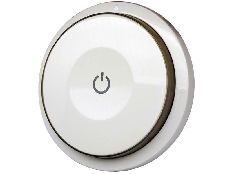
Smart Color Button
SKU: PHIEPSR04


Quickstart
This is a
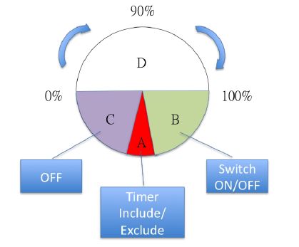
2. Rotate to area A and then press button three times within 1.5 seconds to enter the inclusion mode.
3. After add successful, the device will wake to receive the setting command from Z-Wave Controller about 20 seconds.
Important safety information
Please read this manual carefully. Failure to follow the recommendations in this manual may be dangerous or may violate the law. The manufacturer, importer, distributor and seller shall not be liable for any loss or damage resulting from failure to comply with the instructions in this manual or any other material. Use this equipment only for its intended purpose. Follow the disposal instructions. Do not dispose of electronic equipment or batteries in a fire or near open heat sources.What is Z-Wave?
Z-Wave is the international wireless protocol for communication in the Smart Home. This device is suited for use in the region mentioned in the Quickstart section.
Z-Wave ensures a reliable communication by reconfirming every message (two-way communication) and every mains powered node can act as a repeater for other nodes (meshed network) in case the receiver is not in direct wireless range of the transmitter.
This device and every other certified Z-Wave device can be used together with any other certified Z-Wave device regardless of brand and origin as long as both are suited for the same frequency range.
If a device supports secure communication it will communicate with other devices secure as long as this device provides the same or a higher level of security. Otherwise it will automatically turn into a lower level of security to maintain backward compatibility.
For more information about Z-Wave technology, devices, white papers etc. please refer to www.z-wave.info.
Product Description
This device is a multiple functions button switch. It is able to switch the appliances on/off or adjust the percentage of dimmer.
It can also work as a timer. The well designed wall bracket and magnetic back let the switch can be fixed on the wall. This product can be included and operated in any Z-Wave network with other Z-Wave certified devices from other manufacturers and/or other applications.
Prepare for Installation / Reset
Please read the user manual before installing the product.
In order to include (add) a Z-Wave device to a network it must be in factory default state. Please make sure to reset the device into factory default. You can do this by performing an Exclusion operation as described below in the manual. Every Z-Wave controller is able to perform this operation however it is recommended to use the primary controller of the previous network to make sure the very device is excluded properly from this network.
Reset to factory default
This device also allows to be reset without any involvement of a Z-Wave controller. This procedure should only be used when the primary controller is inoperable.
1. Rotate to area A and then press button four times within 1.5 seconds and do not release the button in the 4 th pressed, and the red LED will light ON.
2. After the red LED goes out, release the button within 2 seconds. 3. IDs are removed and all settings will reset to factory default.
Safety Warning for Batteries
The product contains batteries. Please remove the batteries when the device is not used. Do not mix batteries of different charging level or different brands.
Inclusion/Exclusion
On factory default the device does not belong to any Z-Wave network. The device needs to be added to an existing wireless network to communicate with the devices of this network. This process is called Inclusion.
Devices can also be removed from a network. This process is called Exclusion. Both processes are initiated by the primary controller of the Z-Wave network. This controller is turned into exclusion respective inclusion mode. Inclusion and Exclusion is then performed doing a special manual action right on the device.
Inclusion
Rotate to area A and then press button three times within 1.5 seconds to enter the inclusion mode.Exclusion
Rotate to area A and then press button three times within 1.5 seconds to enter the exclusion mode. Node ID has been removed.Product Usage
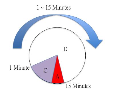
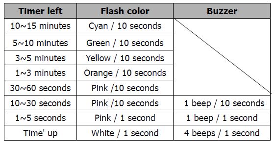
Timer
Communication to a Sleeping device (Wakeup)
This device is battery operated and turned into deep sleep state most of the time to save battery life time. Communication with the device is limited. In order to communicate with the device, a static controller C is needed in the network. This controller will maintain a mailbox for the battery operated devices and store commands that can not be received during deep sleep state. Without such a controller, communication may become impossible and/or the battery life time is significantly decreased.
This device will wakeup regularly and announce the wakeup state by sending out a so called Wakeup Notification. The controller can then empty the mailbox. Therefore, the device needs to be configured with the desired wakeup interval and the node ID of the controller. If the device was included by a static controller this controller will usually perform all necessary configurations. The wakeup interval is a tradeoff between maximal battery life time and the desired responses of the device. To wakeup the device please perform the following action: After the device adding to the network, it will wake-up once per day in default. When it wake-up it will broadcast the “Wake Up Notification†message to the network, and wake-up 20 seconds for receive the setting commands. The wake-up interval minimum setting is 30 minutes, and maximum setting is 120 hours. And the interval step is 30 minutes. If the user wants to wake-up the device immediately, please rotate to area A and then press the button once. The device will wake-up 10 seconds.
Quick trouble shooting
Here are a few hints for network installation if things dont work as expected.
- Make sure a device is in factory reset state before including. In doubt exclude before include.
- If inclusion still fails, check if both devices use the same frequency.
- Remove all dead devices from associations. Otherwise you will see severe delays.
- Never use sleeping battery devices without a central controller.
- Dont poll FLIRS devices.
- Make sure to have enough mains powered device to benefit from the meshing
Association - one device controls an other device
Z-Wave devices control other Z-Wave devices. The relationship between one device controlling another device is called association. In order to control a different device, the controlling device needs to maintain a list of devices that will receive controlling commands. These lists are called association groups and they are always related to certain events (e.g. button pressed, sensor triggers, ...). In case the event happens all devices stored in the respective association group will receive the same wireless command wireless command, typically a 'Basic Set' Command.
Association Groups:
| Group Number | Maximum Nodes | Description |
|---|---|---|
| 1 | 8 | Z-Wave Plus Lifeline. The group 1 is for receiving the report message, like triggered event, temperature, humidity etc. |
| 2 | 8 | Lighting control group |
Configuration Parameters
Z-Wave products are supposed to work out of the box after inclusion, however certain configuration can adapt the function better to user needs or unlock further enhanced features.
IMPORTANT: Controllers may only allow configuring signed values. In order to set values in the range 128 ... 255 the value sent in the application shall be the desired value minus 256. For example: To set a parameter to 200 it may be needed to set a value of 200 minus 256 = minus 56. In case of a two byte value the same logic applies: Values greater than 32768 may needed to be given as negative values too.
Parameter 1: Basic Set OFF level
Control the value representedby the left-side in area D. E.g. Setting this configuration to 16 means range of Command Basic Set value start from 16 Size: 1 Byte, Default Value: 0
| Setting | Description |
|---|---|
| 0 - 99 | Control the value represented by the left-side in area D. |
Parameter 2: Basic Set ON level
Control the value representedby the right-side in area D. E.g. Setting this configurationto 30 means range of Command Basic Set value start from 30 Size: 1 Byte, Default Value: 99
| Setting | Description |
|---|---|
| 0 - 99 | Control the value represented by the right-side in area D. |
Parameter 10: Auto Report Battery Time
The interval time for auto report the battery level. 0 means turn off auto report battery. The default value is 12. The value is in minutes.Each unit means 30 minutes Size: 1 Byte, Default Value: 12
| Setting | Description |
|---|---|
| 0 - 127 | The interval time for auto report the battery level. |
Parameter 25: Customer Function
Customer defined function Bitset: 1 + 2 = 3 Size: 1 Byte, Default Value: 0
| Setting | Description |
|---|---|
| 1 | Dimmer setting method. 0 : Auto send Command Basic Set after rotating. 1 : Send Command Basic Set by touching key after rotating |
| 2 | Disable buzzer in timer mode. 0: Enable. 1: Disable. |
Parameter 26: Disable Scene Holding report
Send Central Scene Holding when the button is held. Size: 1 Byte, Default Value: 0
| Setting | Description |
|---|---|
| 0 | Enable |
| 1 | Disable |
Technical Data
| Dimensions | 71x17 mm |
| Weight | 52 gr |
| Hardware Platform | SD3502 |
| EAN | 4713698571542 |
| IP Class | IP 20 |
| Battery Type | 1 * 3,7 V Lithium |
| Device Type | Wall Controller |
| Network Operation | Portable Slave |
| Firmware Version | 01.07 |
| Z-Wave Version | 04.05 |
| Certification ID | ZC10-15090007 |
| Z-Wave Product Id | 0x013c.0x0009.0x0022 |
| Frequency | Europe - 868,4 Mhz |
| Maximum transmission power | 5 mW |
Supported Command Classes
- Basic
- Association Grp Info
- Device Reset Locally
- Central Scene
- Zwaveplus Info
- Configuration
- Manufacturer Specific
- Powerlevel
- Firmware Update Md
- Battery
- Wake Up
- Association
- Version
- Multi Cmd
- Security
Controlled Command Classes
- Basic
Explanation of Z-Wave specific terms
- Controller — is a Z-Wave device with capabilities to manage the network. Controllers are typically Gateways,Remote Controls or battery operated wall controllers.
- Slave — is a Z-Wave device without capabilities to manage the network. Slaves can be sensors, actuators and even remote controls.
- Primary Controller — is the central organizer of the network. It must be a controller. There can be only one primary controller in a Z-Wave network.
- Inclusion — is the process of adding new Z-Wave devices into a network.
- Exclusion — is the process of removing Z-Wave devices from the network.
- Association — is a control relationship between a controlling device and a controlled device.
- Wakeup Notification — is a special wireless message issued by a Z-Wave device to announces that is able to communicate.
- Node Information Frame — is a special wireless message issued by a Z-Wave device to announce its capabilities and functions.