Philio Tech
Z-Wave 4 in 1 Sensor
SKU: PHI_PST02-1A


Quickstart
This is a
Important safety information
Please read this manual carefully. Failure to follow the recommendations in this manual may be dangerous or may violate the law. The manufacturer, importer, distributor and seller shall not be liable for any loss or damage resulting from failure to comply with the instructions in this manual or any other material. Use this equipment only for its intended purpose. Follow the disposal instructions. Do not dispose of electronic equipment or batteries in a fire or near open heat sources.What is Z-Wave?
Z-Wave is the international wireless protocol for communication in the Smart Home. This device is suited for use in the region mentioned in the Quickstart section.
Z-Wave ensures a reliable communication by reconfirming every message (two-way communication) and every mains powered node can act as a repeater for other nodes (meshed network) in case the receiver is not in direct wireless range of the transmitter.
This device and every other certified Z-Wave device can be used together with any other certified Z-Wave device regardless of brand and origin as long as both are suited for the same frequency range.
If a device supports secure communication it will communicate with other devices secure as long as this device provides the same or a higher level of security. Otherwise it will automatically turn into a lower level of security to maintain backward compatibility.
For more information about Z-Wave technology, devices, white papers etc. please refer to www.z-wave.info.
Product Description
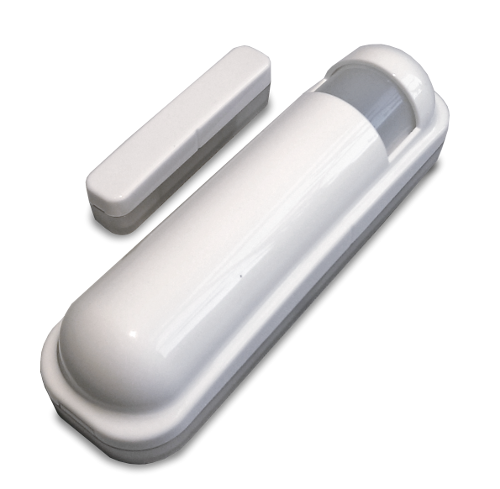
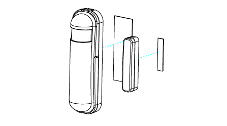
The Philio 4-in-1 Sensor is a Z-Wave door/ window sensor, motion sensor, luminescence sensor and temperature sensor in one package. Thanks to this the PST02-1A can be uses as a security device or home automation device, e.g. to send an alarm when a motion is detected, turn the light on/ off automatically at night or to adjust the heater. The product consists of two elements - the detector and the magnet. The magnet is mounted on the moving part of the window or of the door. The other part is placed on the frame. Note: The illumination sensor does not work with Fibaro Homecenter 2 and Zipabox yet.
When included securely the device is able to accept secure commands and to send secure commands to other devices. The commands and the receiver of the commands sent out on single click and on double click of the rocker can be defined in configuration parameters and association groups.
Download high resolution images for Philio products.
Prepare for Installation / Reset
Please read the user manual before installing the product.
In order to include (add) a Z-Wave device to a network it must be in factory default state. Please make sure to reset the device into factory default. You can do this by performing an Exclusion operation as described below in the manual. Every Z-Wave controller is able to perform this operation however it is recommended to use the primary controller of the previous network to make sure the very device is excluded properly from this network.
Reset to factory default
This device also allows to be reset without any involvement of a Z-Wave controller. This procedure should only be used when the primary controller is inoperable.
- Press the tamper button four times within 1.5 seconds and do not release the tamper button at the 4th button and the LED will light up.
- After 3 seconds, the LED will turn off, then release the tamper button within 2 seconds. If this is successful, the LED will light up for one second. Otherwise the LED flashes once.
- IDs are excluded and all settings are reset to the factory settings.
Safety Warning for Batteries
The product contains batteries. Please remove the batteries when the device is not used. Do not mix batteries of different charging level or different brands.
Installation
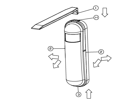
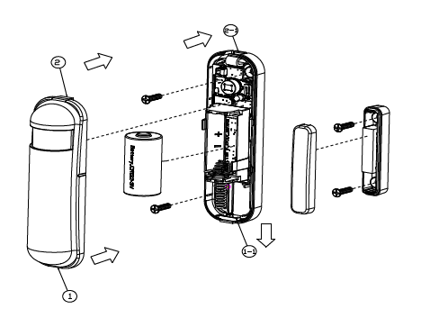
If the device reports the battery message. The user should replace the battery. The battery type is CR123A, 3.0V. Please follow the steps below to open the front cover.
- Use a tool to press the 1-1 position to release the cover.
- Hold the front cover and pull it back
- Hold the front cover and pull upwards
- The recommended mounting height is 160cm.
- Do not let the device to the window or sunlight. For example, the heater or air conditioner.
Installation
- Add the device to the Z-WaveTM network for the first time. First, make sure that the primary controller is in inclusion mode. And then turn on the device, just remove the insulation on the back of the device. The device will start the NWI (network wide inclusion) mode automatically. And it should be included in 5 seconds. The LED indicator will be on for one second.
- Leave the control with the device in the first group. Any light switch that should be turned on when the device triggers, put in the second group.
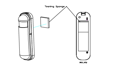
- There are two types of double coated tape in the accessory pack, one is thicker (hereafter referred to as A tape) and another is thinner (hereafter referred to as B tape), you can use the A tape for the test at the beginning. The correct way for tape installation is to hold it at the position below the tamper button. The thicker tape is not suitable when the tamper button is pressed, so the sensor will enter the test mode. You can test if you have chosen the optimal position.
Inclusion/Exclusion
On factory default the device does not belong to any Z-Wave network. The device needs to be added to an existing wireless network to communicate with the devices of this network. This process is called Inclusion.
Devices can also be removed from a network. This process is called Exclusion. Both processes are initiated by the primary controller of the Z-Wave network. This controller is turned into exclusion respective inclusion mode. Inclusion and Exclusion is then performed doing a special manual action right on the device.
Inclusion
- Pressing the sabotage key three times (three times within 1.5 seconds), you enter the inclusion mode.
Exclusion
- By pressing the sabotage key three times (three times within 1.5 seconds), you enter the exclusion mode.
Quick trouble shooting
Here are a few hints for network installation if things dont work as expected.
- Make sure a device is in factory reset state before including. In doubt exclude before include.
- If inclusion still fails, check if both devices use the same frequency.
- Remove all dead devices from associations. Otherwise you will see severe delays.
- Never use sleeping battery devices without a central controller.
- Dont poll FLIRS devices.
- Make sure to have enough mains powered device to benefit from the meshing
Association - one device controls an other device
Z-Wave devices control other Z-Wave devices. The relationship between one device controlling another device is called association. In order to control a different device, the controlling device needs to maintain a list of devices that will receive controlling commands. These lists are called association groups and they are always related to certain events (e.g. button pressed, sensor triggers, ...). In case the event happens all devices stored in the respective association group will receive the same wireless command wireless command, typically a 'Basic Set' Command.
Association Groups:
| Group Number | Maximum Nodes | Description |
|---|---|---|
| 1 | 8 | Transmitting the message, such as triggered event, temperature, lighting, etc. |
| 2 | 8 | Light control, the device sends Basic Set CC to this group |
Configuration Parameters
Z-Wave products are supposed to work out of the box after inclusion, however certain configuration can adapt the function better to user needs or unlock further enhanced features.
IMPORTANT: Controllers may only allow configuring signed values. In order to set values in the range 128 ... 255 the value sent in the application shall be the desired value minus 256. For example: To set a parameter to 200 it may be needed to set a value of 200 minus 256 = minus 56. In case of a two byte value the same logic applies: Values greater than 32768 may needed to be given as negative values too.
Parameter 2: Basic Set Level
Setting the BASIC command value to turn on the light. Size: 1 Byte, Default Value: 255
| Setting | Description |
|---|---|
| 0 | Disabled |
| 1 - 100 | Dimming value in % |
| 254 | Enabled |
Parameter 3: PIR sensitivity
High sensitivity means that long distances can be detected, but if there is more noise in the environment, there may be more false triggering. Size: 1 Byte, Default Value: 80
| Setting | Description |
|---|---|
| 0 | Disabled |
| 1 - 99 | 1 is the lowest sensitivity ,99 is the highest sensitivity. |
Parameter 4: Trigger limit for light
Setting the illumination threshold to turn on the light. When the event is triggered and the ambient illumination is lower than the threshold, the device turns on the light. Size: 1 Byte, Default Value: 99
| Setting | Description |
|---|---|
| 0 | Disabled |
| 1 - 99 | 1 means darkest 99 means lightest. |
Parameter 5: Operating mode
The reserve bit is arbitrary, but without effect Size: 1 Byte, Default Value: 0
| Setting | Description |
|---|---|
| 1 | Reserve. |
| 2 | 1 means test mode, 0 means normal mode. Note: This bit only effect by DIP switch setting to Customer Mode, otherwise it decides by DIP switch setting to Test or Normal Mode. |
| 4 | Disabled Door/window function 1:Disabled 0:Enabled |
| 8 | Setting the temperature scale. 0: Fahrenheit, 1: Celsius |
| 16 | Disable the lighting report after the event is triggered. (1: Disable, 0: Enable) |
| 32 | Disable the temperature report after event triggering. (1: Disable, 0: Enable) |
| 64 | Reserve. |
| 128 | Reserve |
Parameter 6: Multi-sensor function switching
Multisensor switching function - values can be added together 1+2=3 Size: 1 Byte, Default Value: 4
| Setting | Description |
|---|---|
| 1 | Deactivates the integrated magnetic contact, the brightness sensor controls the devices in group 2 (1: deactivate, 0: activate) |
| 2 | Disables the integrated PIR, the brightness sensor controls the devices in group 2 (1:Disabled; 0:Enabled). |
| 4 | Disable the magnetic integration of the PIR to turn on the lighting nodes in the assignment group 2. (1:Disable, 0:Enable) |
| 8 | If bit2 is 0 (Enable), are the device and the lighting in the same room? 0: In the same room (default), 1: In another room. |
| 16 | Disables the 5 seconds delay before the light is turned off, when closing the window or door (1: Disable, 0: Enable). |
| 32 | Disables automatic shutdown, light turns on only. (1: Disable, 0: Enable) |
| 64 | Reserve |
| 128 | Reserve |
Parameter 7: User defined functions
Values can be added together 1+2=3 Size: 1 Byte, Default Value: 4
| Setting | Description |
|---|---|
| 1 | Reserve |
| 2 | Enable sending the movement OFF report. (0:Disable, 1:Enable) |
| 4 | Enable the PIR super sensitivity mode. (0:Disable, 1:Enable) |
| 8 | Deactivates the Basic Off area after closing the door (0: Deactivated; 1: Activated). |
| 32 | Disables the Multi CC command class in the Automatic Report (0: Disabled; 1: Enabled). |
| 32 | Disables the Multi CC command class in the Automatic Report (0: Disabled; 1: Enabled). |
| 64 | Disables the battery report (0: Disabled; 1: Enabled). |
| 128 | Reserve |
Parameter 8: PIR recognition time
In normal mode, after the motion is detected, set the reacquisition time. 8 seconds per tick, default tick is 3 (24 seconds) .Set the appropriate value to prevent the trigger signal from being received too frequently. This can also save battery. Size: 1 Byte, Default Value: 3
| Setting | Description |
|---|---|
| 1 - 127 | Time 8 x value = time in seconds |
Parameter 9: Switch-off time
This value becomes active after the lighting is switched on. Here the switch-off delay after detection of a movement is defined. 8 seconds per tick, default tick is 4 (32 seconds). Size: 1 Byte, Default Value: 4
| Setting | Description |
|---|---|
| 0 - 127 | Delay 8 x value = time in seconds |
Parameter 10: Automatic battery report
The interval time for the automatic reporting of the battery status. - The tick time can be set by configuration No. 20. Size: 1 Byte, Default Value: 12
| Setting | Description |
|---|---|
| 0 - 127 | Time in seconds |
Parameter 11: Automatic report of the door/window status after time
The interval time for the automatic message of the door / window state. The tick time can be set by configuration No. 20. Size: 1 Byte, Default Value: 12
| Setting | Description |
|---|---|
| 0 - 127 | Time in seconds |
Parameter 12: Automatic report brightness by time
The interval time for the automatic display of brightness. The tick time can be set by configuration no. 20. Size: 1 Byte, Default Value: 12
| Setting | Description |
|---|---|
| 0 - 127 | Time in seconds |
Parameter 13: Automatic report by time for temperature
The interval time for the automatic display of the temperature. The tick time can be set by configuration no. 20. Size: 1 Byte, Default Value: 12
| Setting | Description |
|---|---|
| 0 - 127 | Time in seconds |
Parameter 20: Automatic report tick interval
The interval time for automatic reporting of each tick. Setting this configuration will enable configuration No.10, No.11, No.12 and No.13. Attention: Setting to 0 means that all automatic reporting functions are disabled. Size: 1 Byte, Default Value: 30
| Setting | Description |
|---|---|
| 0 - 255 | Tick interval |
Parameter 21: Temperature difference report
Size: 1 Byte, Default Value: 1
| Setting | Description |
|---|---|
| 0 | Disabled |
| 1 - 127 | in °F |
Parameter 22: Brightness difference report
Size: 1 Byte, Default Value: 0
| Setting | Description |
|---|---|
| 0 | Disabled |
| 1 - 100 | in % |
Technical Data
| Dimensions | 95x28x35 mm |
| Weight | 48 gr |
| Hardware Platform | ZM5202 |
| EAN | 4713698570163 |
| IP Class | IP 20 |
| Battery Type | 1 * CR123A |
| Device Type | Notification Sensor |
| Network Operation | Reporting Sleeping Slave |
| Z-Wave Version | 6.51.02 |
| Certification ID | ZC10-14080012 |
| Z-Wave Product Id | 0x013C.0x0002.0x000C |
| Frequency | Europe - 868,4 Mhz |
| Maximum transmission power | 5 mW |
Supported Command Classes
- Association
- Association Group Information
- Battery
- Sensor Binary
- Configuration
- Device Reset Locally
- Firmware Update Md
- Manufacturer Specific
- Multi Command
- Sensor Multilevel
- Notification
- Powerlevel
- Security
- Version
- Wake Up
- Zwaveplus Info
Controlled Command Classes
- Basic
Explanation of Z-Wave specific terms
- Controller — is a Z-Wave device with capabilities to manage the network. Controllers are typically Gateways,Remote Controls or battery operated wall controllers.
- Slave — is a Z-Wave device without capabilities to manage the network. Slaves can be sensors, actuators and even remote controls.
- Primary Controller — is the central organizer of the network. It must be a controller. There can be only one primary controller in a Z-Wave network.
- Inclusion — is the process of adding new Z-Wave devices into a network.
- Exclusion — is the process of removing Z-Wave devices from the network.
- Association — is a control relationship between a controlling device and a controlled device.
- Wakeup Notification — is a special wireless message issued by a Z-Wave device to announces that is able to communicate.
- Node Information Frame — is a special wireless message issued by a Z-Wave device to announce its capabilities and functions.